User-defined building grids help you to model structures consisting of surfaces, girder grillages, or grids. The intersection points of a planar or spatial grid consisting of lines represent definition points for lines, members, and surfaces. You can use a building grid for setting objects, provided that the object snap is activated by the "Building Grid" option (see the chapter Object Snaps). You can also do it by quick control using the
 button in the
CAD Toolbar
.
button in the
CAD Toolbar
.
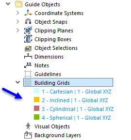
Four grid types are preset, which you can adjust, if necessary, and use for input.
In the "New Building Grid" dialog box, you can create a user-defined grid.
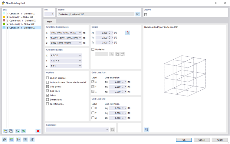
You can also define a new building grid using the
 button in the CAD toolbar.
The Active check box controls whether the selected grid is displayed in the work window.
Main
In the Main tab, you define the basic specifications for the building grid.
Grid Line Coordinates
Enter the position coordinates of the grid lines in this dialog section. Use spaces as separators (see Dialog Box "New Building Grid"). Make sure that the coordinates are consistently in ascending or descending order.
For a regular grid, enter the coordinate of the first line. Then, add the number of other grid lines and multiply the value by the distance (example: 4*5,000 means "Four additional lines, each at a distance of 5,000 m").
When you create a specific grid by a rotation (cylindrical or spherical), you can define the rotation angles and distances in the customized text boxes.
Grid Line Labels
In this section, specify the descriptions you want give to the grid lines. The entries set by default are automatically added when you insert coordinates in the section above. Again, the tooltip provides useful information.
Origin
Place the zero point of the grid in an existing or new "Node". You can also place the origin in any point by entering its coordinates or defining the point graphically with the
 button.
Options
In this section, you can set the display of the building grid individually:
- Lock in graphics: The grid cannot be moved graphically.
- Include in view "Show whole model": The grid is shown in the overall view.
- Grid points: The intersection points of the grid lines are displayed.
- Grid lines: The grid lines are displayed.
- Labels: The descriptions of the grid lines are displayed if the "Label" options for the grid line start and the grid line end are activated.
- Dimensions: The dimensions of the grid points are displayed.
- Specific grid: The line grid can be inclined, rotated, or aligned with a reference object (see the Specific Grid tab).
Grid Line Start/Grid Line End
You can extend the grid lines beyond the boundary intersection points of the lines by a "line extension". Specify the dimensions for the relevant axes.
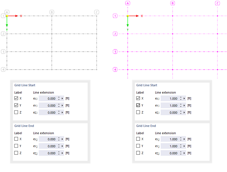
The "Label" check boxes control whether the descriptions are displayed on the grid lines and for which axes and line ends the labels are shown.
Specific Grid
The Specific Grid tab is displayed if you have selected the "Specific grid" option in the "Main" tab. Here, you can change the grid type, rotate the grid, or align it with another object.
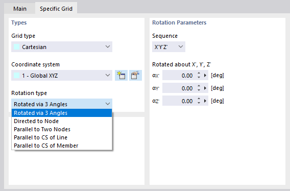
Types
The "Grid type" describes the basic geometric shape of the building grid. The following options are available for selection in the list:
- Cartesian: The grid is created in the Cartesian coordinate system.
- Inclined: The orthogonally oriented grid is rotated by an inclination angle.
- Cylindrical: The grid is created by rotating points about the Z-axis.
- Spherical: The grid is created by rotating points about two axes.
Define the "Coordinate system" to which the building grid refers. You can select a user-defined coordinate system from the list or create a new one using the
 button.
The "Rotation type" defines how the building grid is rotated. The following options are available for selection in the list:
- Rotated via 3 Angles: Rotation of grid about global axes by angles αX', αY', and αZ'
- Directed to Node: Alignment of grid axes X' and Y' to a node
- Parallel to Two Nodes: Alignment of grid to connection line of two nodes
- Parallel to CS of line/member: Alignment of grid to local axes of a line or member
Rotation Parameters
This dialog box section is adapted to the "Rotation type". Here, you can define the objects or rotation angles.
Inclination Angles
This dialog section is displayed for the "Inclined" grid type. You can define the rotation angles α about the axes X, Y, and Z.