


The Chamfer function in the "Edit" menu → "Manipulation" allows you to rotate selected objects while adjusting the coordinate in one direction only. The other two direction coordinates are kept.
For example, chamfering makes it easier to change the inclination of members of a roof surface: The member lengths are adjusted to the new Z-coordinate, while the coordinates in the XY-plane remain unchanged.
Copy
If the "Create copy" check box is not selected, the selected objects will be chamfered. If you want to create a copy, select the check box.
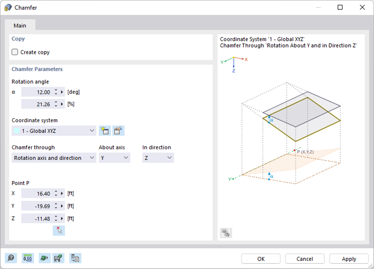
Chamfer Parameters
Enter the "Rotation angle" α. It is related to a clockwise coordinate system of the "axis" that you define below. The dialog graphic shows the axes with positive angles. You can enter the angle in [°] or [%]. Both text boxes are interactive.
Define the "Coordinate system" in which the objects are to be rotated. You can select a user-defined coordinate system from the list or create a new one with the
![]() button.
button.
The "Chamfer through" list provides two options for defining the direction of chamfering:
- Rotation axis and direction: The rotation axis runs parallel to an axis of the specified coordinate system. Select it in the "About axis" list. Then, set the coordinate to be adjusted in the "In direction" list. Enter the "Point P" that lies on the rotation axis to define the position of the axis.
- Perpendicular via 3 points: The rotation axis lies anywhere in space. Enter the coordinates for "Point P1" and "Point P2" to define the rotation axis. Then, define the plane and the direction by "Point P3". You can also define the three points graphically with the
 button.