


The load wizard for load models makes it possible to compile different loads in a load model and apply them as a load arrangement.

Load models are required to apply moving loads to surfaces or members using the load wizard for moving loads.
If different moving loads move parallel or with an offset on surfaces, use the
![]() button at the bottom of the "List" to create another load model. This allows you to individually control the movements of the loads in a set of movements.
button at the bottom of the "List" to create another load model. This allows you to individually control the movements of the loads in a set of movements.
Generation on
Select from the list the objects on which the loads from the load model are to be generated:
- On surfaces
- On members
Load Components
In this section, you can define the load parameters. The input options are tailored to the load type and explained in the dialog graphic; they also differ for surfaces and members.
Number of Load Components
Specify how many loads are present in the load position. A category is added for each additional component of this “load block”. You can use the load components to describe the moving load via forces and moments.
Load Component – Categories
These categories control which parameters you can define further down the line.
Load Type
The following options are available for selection in the list:
- Force: The load is a directed quantity.
- Moment: The load is a product of force and lever arm.
Coordinate System
If the load does not refer to the global coordinate system XYZ, you can select a user-defined coordinate system from the list or create a new one.
Load Direction
Use the list to specify the direction in which the load acts. Depending on the coordinate system, the global axes X, Y, Z or the user-defined axes U, V, W are available for selection. The load can be related to the true length (index "L") or the projected length (index "P") of lines.
Load Component – Type of Load
The list provides various options for displaying the arrangement of the load.
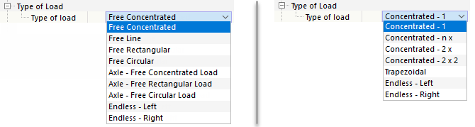
The following table briefly describes the load types. You can specify the parameters in the next category.
| Load Type | Load Symbol | Description |
|---|---|---|
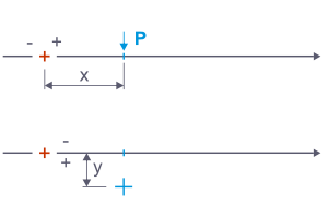
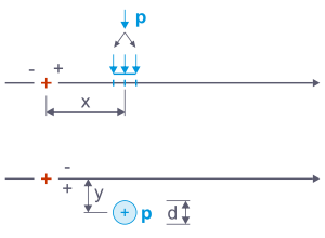
| Free concentrated load (single force, concentrated moment) | Specify the load magnitude "P" or "M" and the distance of the load "x" longitudinally and "y" transversely to the fixed point of the load position. | |
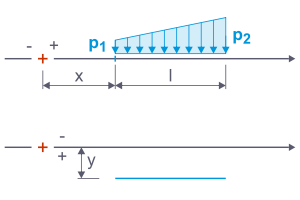
| Free line load (uniform load, trapezoidal load) | Specify the forces "p1" and "p2", the distance "x" and "y", and the length "l" of the line load. | |
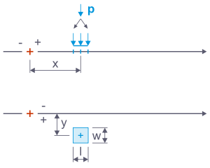
| Free rectangular load (area block load) | Specify the distance "x" and "y", as well as the force "P". This force is converted into a surface load that acts on the width "w" and length "l" to be defined. | |
| Free circular load (area round load) | Specify the distance "x" and "y", as well as the force "P". This force is converted into a circular surface load that acts on the diameter "d" to be defined. | |
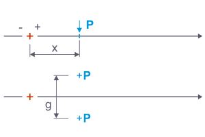
| Axle - free concentrated load (force pair, moment pair) | The load "P" or "M" is distributed over two individual loads at a distance of the gauge "g". Specify the distance "x" to the fixed point of the load position. | |
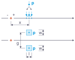
| Axle – free rectangular load (block load pair) | The load "P" is distributed over two surface loads at a distance of the gauge "g". These each act on the width "w" and length "l" (for example, the wheel contact area). | |
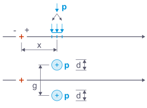
| Axle – free circular load (round load pair) | The load "P" is distributed over two surface loads at a distance of the gauge "g". These each act on a circular area with a diameter "d" to be defined. | |
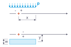
| Endless – Left (uniformly distributed load) | At each load position, a constant load is applied which acts up to the start of the line set. Specify the load magnitude "p", the width "w", and the distance "x" of the right edge of the load to the load step's fixed point. You can use the distance "y" to offset the load transversely to the moving line. | |
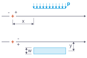
| Endless – Right (uniformly distributed load) | At each load position, a constant load is applied which acts up to the end of the line set. In this case, specify the distance "x" of the left edge of the load to the load step's fixed point. |
Load Types for Members
| Load Type | Load Symbol | Description |
|---|---|---|
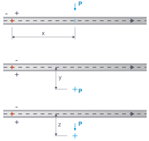
| Concentrated – 1 (concentrated load, concentrated moment) | Enter the load size "P" or "M", the distance "x" of the load along the fixed point of the load position, and the eccentricities "y" and "z" transverse to the moving line. | |
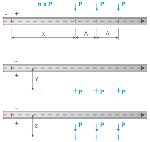
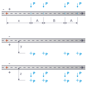
| Concentrated – n x (concentrated loads, concentrated moments) | Concentrated loads of equal size act at a constant distance from each other. Enter the load size, the distance "x" of the first load to the fixed point of the load position, the distance "A" between the loads, and the eccentricities "y" and "z" transverse to the moving line. | |
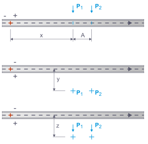
| Concentrated – 2 x (force pair, moment pair) | Two concentrated loads of different sizes move along the members. Enter the load size, the distance "x" of the first load to the fixed point of the load position, the distance "A" between the loads, and the eccentricities "y" and "z" transverse to the moving line. | |
| Concentrated – 2 x 2 (force pair, moment pair) | Two pairs of loads with equal concentrated loads move along the members. Enter the load size, the distance "x" of the first load to the fixed point of the load position, the distances "A" between the loads of a load pair and "B" between the load pairs, and the eccentricities "y" and "z" transverse to the moving line. | |
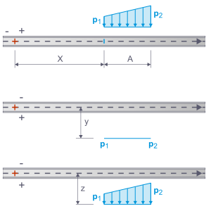
| Trapezoidal (uniformly distributed load, trapezoidal load) | Enter the forces "p1" and "p2", the distance "x" to the fixed point of the load position, the length "A" of the uniform load, and the eccentricities "y" and "z" transverse to the moving line. | |
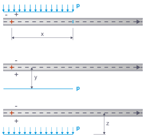
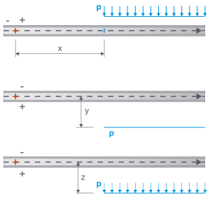
| Endless – Left (uniformly distributed load) | A constant load is applied at each load position, which acts up to the start of the member or member set. Enter the load magnitude "p" and the distance "x" of the right load edge to the load step's fixed point. You can use the eccentricities "y" and "z" to offset the load transversely to the moving line. | |
| Endless – Right (uniformly distributed load) | A constant load is applied at each load position and acts up to the end of the member or member set. Specify the load size "p" and the distance "x" of the left load edge to the load step's fixed point. With the eccentricities "y" and "z", you can offset the load transversely to the moving line. |
Load Component – Parameters
The parameters are matched to the load type that you have previously defined. The meaning of the parameters is shown in symbolic form in the graphics area on the right.
Position x
The location x describes the distance of the load to the load step's fixed point along the moving line. This fixed point is symbolized by a red cross in the sketch.
Position y / Eccentricity y
This entry makes it possible to place loads next to the moving line. A positive value positions the load to the right of the moving line in the viewing direction, a negative value to the left of it.
Eccentricity z
This specification allows for member loads to be placed below or above the moving line. A positive value assigns the load to the side of the positive member axis z.
Gauge g
For axle loads, you can specify the load pair's centroidal distance according to the sketch.
Load Magnitude P / M / p
You can specify the magnitudes of the force P or the moment M for these parameters. For line and distributed loads, enter the load magnitudes p1 at the line start and p2 at the line end. If the two values differ, you have a trapezoidal load.
Width b
For rectangular loads, you can define the load width. It represents the dimension of the load contact area perpendicular to the moving direction.
If an endless load is present, the width of the lane on which the uniformly distributed load acts must be specified in this column.
Length l
Here you can specify the length of the load contact area in the moving direction or the length of the linear load.
The geometric conditions are taken into account when using offsets and bumpers (see the chapter Moving Loads ): The surfaces only receive proportional loads from the contact areas.
