


After importing a CAD file, there is often the problem that corresponding elements in the structural model are not connected. The ‘’‘Rule-Based Link Generator’‘’ feature makes it easier to link objects: The program creates the connection in the form of rigid members and rigid links.

Rule Set
In a "rule set", you can define one or more rules for generating links. They apply to specific object types. You define the details of these rules in the Parameters section.
In the “Active” column, you can control whether a rule should be applied. If you select the checkbox, a new cell for another rule is added automatically.
The “Type” plays an important role in the generation of links: It determines between which object types the links are created. There are several options to select from in the list.
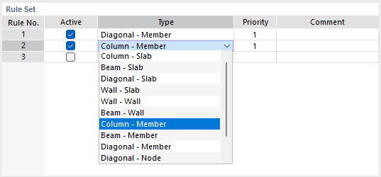
The function of the individual types is described in the following table.
| Type | Linking Objects |
|---|---|
| Column – Slab | Vertical members with horizontal surfaces |
| Beam – Slab | Horizontal members with horizontal surfaces |
| Diagonal – Slab | Inclined members with horizontal surfaces |
| Wall – Slab | Vertical surfaces with horizontal surfaces |
| Wall – Wall | Vertical surfaces with vertical surfaces |
| Beam – Wall | Horizontal members with vertical surfaces |
| Column – Member | Vertical members with members in any location |
| Beam – Member | Horizontal members with members in any location |
| Diagonal – Member | Inclined members with members in any location |
| Diagonal – Node | Inclined members with nodes in the vicinity |
| Column – Node | Vertical members with nodes in the vicinity |
| Beam – Node | Horizontal members with nodes in the vicinity |
The types are based on the following concept: The “source objects” (first designation in the type pair) are connected to the “target objects” (second designation) by the shortest path using nodal links or line links. If necessary, nodes are automatically created on the target objects.
The order of the rules in the rule set also determines the priorities according to which the objects are linked. However, you can change this automatic setting in the “Priority” column by assigning a lower priority (2) to a rule.
Parameters
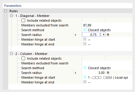
In the lower section, you can specify the details for each rule. In principle, they correspond to the specifications that apply to nodal links or line links.
Search Method
Currently, only the “Nearest Objects” option is available. The program searches for the object (node, member, line, surface) within the defined radius that has the shortest distance to the original object. This object is then rigidly linked with a rigid member or over the relevant length.
Search Radius
The links are only created for objects that are within a certain radius of the original object.
Nodes/Members/Surfaces Excluded from Search
If certain objects within the search area are not to be linked, enter the numbers of these target objects. Use the graphical selection option using the
![]() button, which can be accessed by clicking in the input box.
button, which can be accessed by clicking in the input box.
Include Related Objects
Related objects are automatically excluded from the search. These include integrated objects or definition objects, such as nodes that are used to define the boundary lines of surfaces. If you select this check box, these objects will also be included in the search.
Member Hinge/Line Hinge
By default, objects are connected as rigid. You can also link them as hinged. To do this, select one of the predefined hinges from the list or use the
![]() button to define a new hinge type.
button to define a new hinge type.
Examples
- Link Type: Column – Member
The parameters of Rule 1 are used to generate nodal links for all vertical members of the model with members that are spaced at a maximum distance of 32 cm.

- Link Types Wall – Slab and Wall – Wall
Rules 4 and 5 apply to the connection of surfaces using line links. The parameters of Rule 4 are used to connect all vertical surfaces of the model with horizontal surfaces that are at a maximum distance of 1 m. All vertical surfaces are also linked with a line hinge according to the parameters of Rule 5.


