


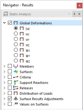
You can display the results for nodes graphically using the Global Deformations and Support Reactions navigator categories. You find the numerical results of nodes in the Results by Node table category.
Global Deformations
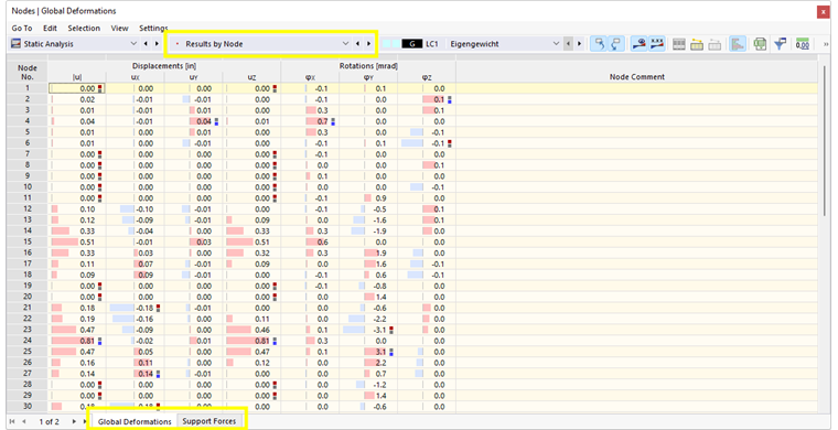
The image Results by Node in Table shows the table with global nodal deformations.
The displacements and rotations mean the following:
| |u| | Absolute value of the total displacement |
| uX | Displacement in the direction of the global axis X |
| uY | Displacement in the direction of the global axis Y |
| uZ | Displacement in the direction of the global axis Z |
| φX | Rotation about the global axis X |
| φY | Rotation about the global axis Y |
| φZ | Rotation about the global axis Z |
You can use the
![]() button to display the deformations as a motion sequence (see the Animation of Deformations feature).
button to display the deformations as a motion sequence (see the Animation of Deformations feature).
Deformation State of Model
The list button in the toolbar allows you to display the shape of the real model in various deformation states.
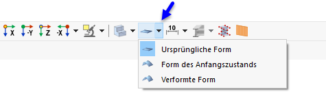
The functions of the buttons are as follows:
| Button | Function |
|---|---|
|
|
Restore the original shape of the model (initial state without load or form-finding) |
|
|
Display the initial state shape, for example, due to a different load case |
|
|
Display the deformed model |
See an example of displaying different shapes in the chapter Results of the Form-Finding manual.
Support Forces
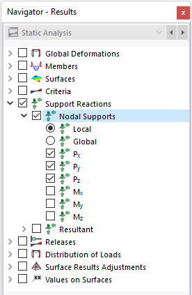
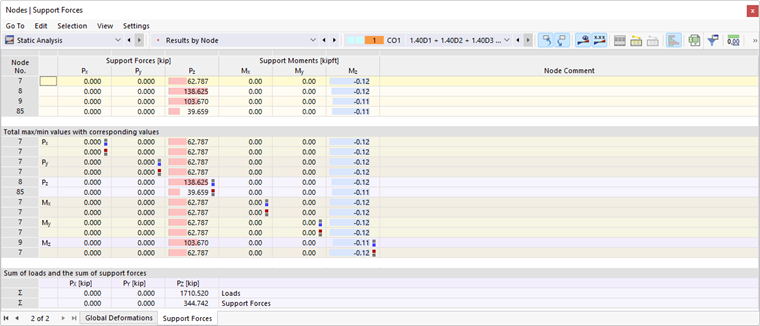
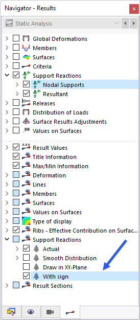
Support forces are designated by "P", support moments by "M". They are usually related to the global axis system. In the navigator, you can specify which components are displayed graphically. Concerning rotated nodal supports, it is also possible to show local support forces.
The table lists the forces and moments that are introduced into the nodal support. Thus, with regard to signs, the table does not show the reaction forces or moments on the part of the support. The signs result from the direction of the global axes. If the global Z-axis is directed downwards, the "self-weight" load case, for example, results in a positive support force PZ, and a wind load against the global X-axis results in a negative support force PX. Thus, the support forces shown in the table represent the foundation loads.
In contrast to the results in the table, the "Support Reactions" vectors in the graphic represent the reaction forces and moments on the part of the supports. The components are visualized by the size and direction of the vectors. You can also display the signs of the introduced forces in the work window by selecting the corresponding entry in the lower section of the navigator. Use this option only for visualizing the introduced forces in order to avoid misunderstandings.
A positive support moment acts clockwise about the corresponding positive global axis. As with the support forces, the vectors already have a mathematical sign, and the values must be considered independently of this: The signs indicate the directions of the moments in relation to the global axes.
Sum of Loads and Sum of Support Forces
For load cases and load combinations, the check sums Σ of loading and support forces are indicated at the end of the table. This balance will show a difference if the model also has line supports, member supports, or surface supports. Those support forces must also be considered in the overall balance.