


You need a section to describe the properties of a member: The section properties and the assigned material properties affect the stiffness of the member.
Not every section that has been defined needs to be used in the model. This way, you can model variants quickly, without deleting cross-sections. However, it is not possible to renumber the sections.

Name
You can define any name for the section and specify its cross-section properties. If the description matches an entry in the library, RFEM imports the stored properties. To select the cross-section from the library, click the
![]() button at the end of the input line. The import of sections is described in the chapter Cross-Section Library.
button at the end of the input line. The import of sections is described in the chapter Cross-Section Library.
For cross-sections from the library, the section properties are set by default and cannot be changed. The shear areas and the dimensions for non-uniform temperature loads are exceptions.
For a user-defined section name, you have to define all section properties manually. You can then use the cross-section to determine the internal forces and moments. However, the design of this cross-section is impossible, because no stress points can be defined.
Main
The Main tab manages the basic section parameters.
Material
It is necessary to assign a material to each cross-section. You can select it from the list of already defined materials. The buttons next to the text box allow you to select a material from the library or to define a new one (see the chapter Materials).
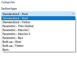
Categories
Section Type
A "Section type" is set by default, corresponding to the usual classifications of cross-sections from the library (see the chapter Cross-Section Library). User-defined cross-sections are assigned to the "Basic" type.
Manufacturing Type
The production method of a cross-section is displayed for the cross-sections from the library. It controls certain design specifications; for example, the buckling curves of cold-formed hollow sections.
Options
Deactivate Shear Stiffness
Taking shear stiffness into account leads to an increase in deformation due to shear forces. Shear deformation plays a minor role in rolled and welded cross-sections. For solid and timber cross-sections, however, we recommend considering the shear stiffnesses for the deformation analysis.
Deactivate Warping Stiffness
The check box for taking the warping stiffness into account is available if the Torsional Warping add-on is activated in the Base Data. In this case, you can control whether the warping stiffness of the cross-section is applied in the calculation with seven degrees of freedom.
Section Rotation
The section rotation describes the angle by which the cross-section is rotated. You can define the rotation angle α' in the Section Rotation tab.
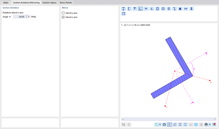
For unsymmetric cross-sections, this tab also provides options to "Mirror" the cross-section. This way, you can put an L-section in the correct position, for example.
When importing a cross-section from the library or RSECTION, you do not need to take care of the section rotation angle α'. RFEM imports the angle automatically. For user-defined cross-sections, however, you have to determine the principal axis angle manually and adjust the position using the section rotation.
Hybrid
The "Hybrid" option is available for cross-sections of the "Parametric – Massive II" type as well as for RSECTION cross-sections consisting of several materials. In the Hybrid tab, you can assign material properties to the components of built-up timber cross-sections.
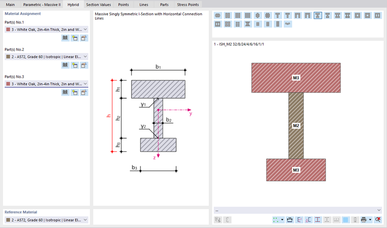
Enter the "Reference Material"—one of the component materials—that you want to use to determine the ideal cross-section properties of the built-up section. The stiffness components of the structural elements are determined in relation to the reference material, taking into account the respective material properties. However, the choice of reference material has no effect on the stiffness of the overall section.
Thin-Walled Model
The "Thin-walled model" check box allows you to control the analysis according to which the cross-section properties are determined for cross-sections of the "Standardized – Steel" and "Parametric – Thin-Walled" type. For a massive section, for example, the shear areas and the torsional moment of inertia are determined according to a different method, since the analytical solution only applies to thin-walled sections.
US Notation for Section Properties
The symbols of the cross-section properties differ according to European and American conventions. You can use the check box to control whether the statical moments are designated as S or Q, for example.
Cost Estimation
Cost estimation is typically based on the costs of the materials assigned to the members of a cross-section (see the chapter Materials). If specific parameters are to apply to a cross-section, you can define the unit costs and units separately in the Cost Estimation tab.
Estimation of CO₂ Emissions
The estimation of CO₂ emissions is also generally based on the material of the cross-section. However, you can also define the unit emissions and units specifically for each cross-section in the CO₂ Emissions Estimation tab.
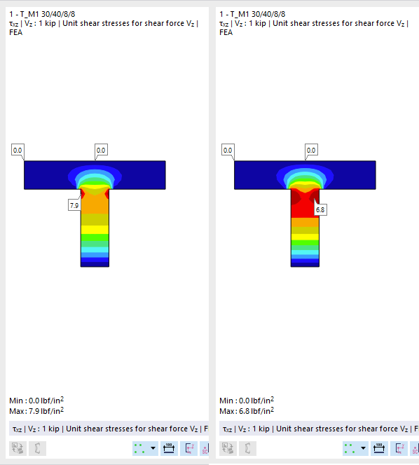
Stress Smoothing to Avoid Singularities
Stress smoothing is primarily suitable for composite timber sections in order to avoid singularities in the connection areas. In these areas, shear stresses often lead to stress peaks, which have an unfavorable effect on the design. This function allows you to achieve a better distribution of stresses.
Section Properties
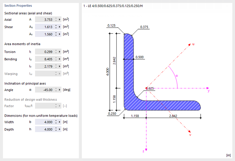
The most important cross-section properties are listed in this section. Further parameters can be found in the Section Values tab.
Sectional Areas
The cross-sectional areas are subdivided into the total area "Axial A", and the areas for "Shear Ay" and "Shear Az". The shear area Ay is related to the moment of inertia Iz; the shear area Az is related to Iy accordingly.
The following technical article provides information on determining shear areas:
The shear areas affect the shear deformation, which should be taken into account especially for short, massive members. If you change the shear areas, you should avoid extremely small values: The shear areas are included in the denominator of equations, so numerical problems may arise.
Area Moments of Inertia
The second moments of area define the section stiffness with regard to loading by moments: The torsional constant IT describes the stiffness against rotation about the longitudinal axis. The second moments of area Iy and Iz describe the stiffnesses against bending about the local axes y and z. Axis y is considered to be the "major" axis. The warping moment of inertia Iω is used to describe the resistance to warping.
For unsymmetric cross-sections, the second moments of area are displayed around the principal axes u and v of the cross-section. The local section axes are shown in the cross-section graphic.
You can adjust the section areas and moments of inertia using factors that you define as a section-specific "structure modification" (see the chapter Structure Modifications).
Inclination of Principal Axes
The inclination of principal axes describes the position of the principal axes in relation to the standard principal axis system of symmetrical cross-sections. For unsymmetrical sections, this is the angle α between the axis y and the axis u (positive in clockwise direction). The principal axes are called y and z for symmetric cross-sections, and u and v for unsymmetric cross-sections (see the image Section Properties and Axes).
The principal axis inclination is determined according to the following equation:
|
α |
Principal axis angle |
|
Iyz |
Biaxial second moment of area |
|
Iz |
Moment of inertia about the z-axis |
|
Iy |
Moment of inertia about the y-axis |
The inclination of principal axes for sections from the library cannot be edited. However, you can rotate the section around a user-defined angle: Select the "Section rotation" check box in the "Options" section (see Section Rotation).
Dimensions (for Non-Uniform Temperature Loads)
The dimensions with regard to the width b and height h of the cross-section are required for the calculation of temperature loads.
RSECTION
If you have a cross-section that was created with RSECTION, you can use the button to open the cross-section program and change the section.
Section Values
In the Section Values tab, the properties of the cross-section are listed in detail.
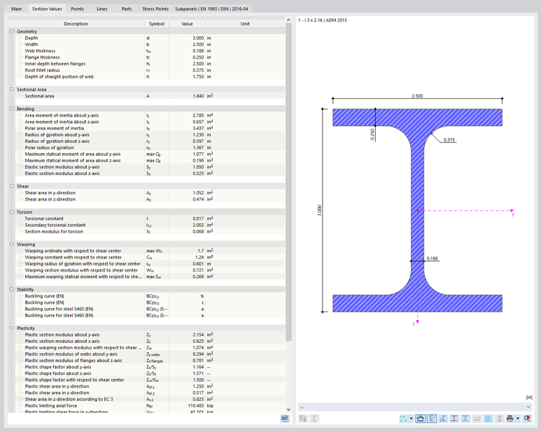
The section properties of parametric cross-sections are determined using RSECTION.
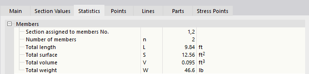
Statistics
The Statistics tab provides an overview of the members available in the model that use that cross-section. For example, you can use the "Total weight" indication for steel schedules or cost estimation.
Points
The geometry of the section is defined by points. They also form the basis for lines.

The coordinates of the definition points are listed in a table. When you select a row, that point is shown in red in the cross-section graphic. For thin-walled sections, the definition points on the center lines are marked with a + symbol. Generated control points for arcs are indicated by a lock symbol with +. The points on the cross-section edges result from the element thicknesses.
For arcs, you can view the arc parameters in the "Parameters" section next to the point coordinates.
Lines
The points of the cross-section are connected by lines, so the geometry of the section is defined by its outline. The lines also form the basis for parts.

The definition points of the lines, as well as the line types and lengths, are listed in a table. When you select a row, that line is shown in red in the cross-section graphic.
Parts
One or more parts are created from the contour lines of the section.

For each cross-section part, the table shows the definition lines, material, cross-section area, and mass per unit length.
Stress Points
Stress points are required to determine the stresses acting on the cross-section. All library sections are provided with stress points at the design-relevant locations of the cross-section.
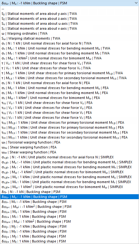
The Stress Points tab consists of up to four sub-tabs. There you can view the coordinates of the stress points, the statical moments and warping coordinates with the associated thicknesses (for thin-walled cross-sections), as well as the unit stresses calculated with the thin-walled analysis TWA (for thin-walled cross-sections) and with the finite element method FEM.

You can check the cross-section distribution and stress curves in the cross-section graphic: Click in the column of the value or select the type from the list below the graphic.
FE Mesh
The last tab manages the settings for the FE mesh, on the basis of which the cross-section values and unit stresses are determined.

The two text boxes allow you to influence the discretization. With a factor smaller than 1, a finer mesh is generated; with a factor greater than 1, a coarser mesh is generated. Generally, no adjustments are required here.
Cost Estimation
The Cost Estimation tab is displayed if you have selected the Cost Estimate option in the ‘‘Main’’ tab.
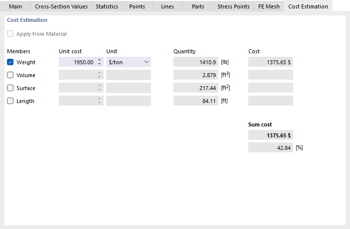
If cost estimation defaults already exist for a cross-section’s material, the “Transfer from Material” check box is selected by default. This applies the member-specific unit cost definitions and prevents duplicate entries. If you want to define unit costs and units separately for members with specific cross-sections, deselect the check box.
Select which cross-section parameter is relevant for the cost estimation: weight, volume, surface, or length. In the “Unit Cost” column, enter the value that one unit of the parameter costs. The “Unit” column list offers various options for unit costs.
The values for weight, surface, solid, and length specified in the “Quantity” column are derived from the properties of the members with the cross-section assigned.
The “Cost” shows the price for all members of the cross-section used. It also represents the “Total Cost”. If multiple cross-sections are enabled for the cost estimation, you can also see the cross-section’s component of the total cost in [%] under Total Cost.
Estimation of CO₂ Emissions
The Estimation of CO₂ Emissions tab appears if you have selected the Estimation of CO₂ Emissions option in the !Main! tab.

If CO₂ emission estimation specifications are already available for a cross-section's material, the “Transfer from Material” check box is selected by default. This ensures that the member-specific emission definitions apply and prevents duplicate specifications. If you want to define the unit emissions and units for members with a specific cross-section separately, deselect the check box.
Select which cross-section parameter is relevant for estimating CO₂ emissions: weight, volume, surface, or length. In the “Unit Emission” column, enter the value representing the CO₂ emissions caused by a parameter unit. The list in the “Unit” column offers various emission units for CO₂ equivalents to select from.
The values displayed in the “Quantity” column for weight, volume, surface, and length are derived from the properties of the members with the cross-section assigned. The “Emission” is calculated from these values and the unit emission.
The “Total Emissions” indicate the CO2 equivalents generated by all members of the cross-section. Furthermore, the component of total emissions attributable to this cross-section is displayed. The “Total Emissions” are calculated by summing the total emissions of each cross-section.