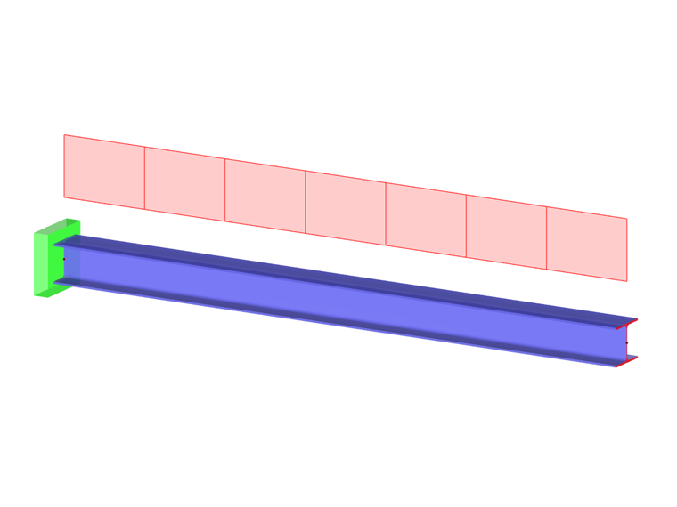
Member loads are forces, moments, masses, temperature effects, or imposed deformations that act on members.
In the list, select the "Load Case" to which you want to assign the load.
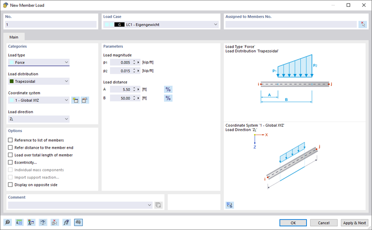
Main
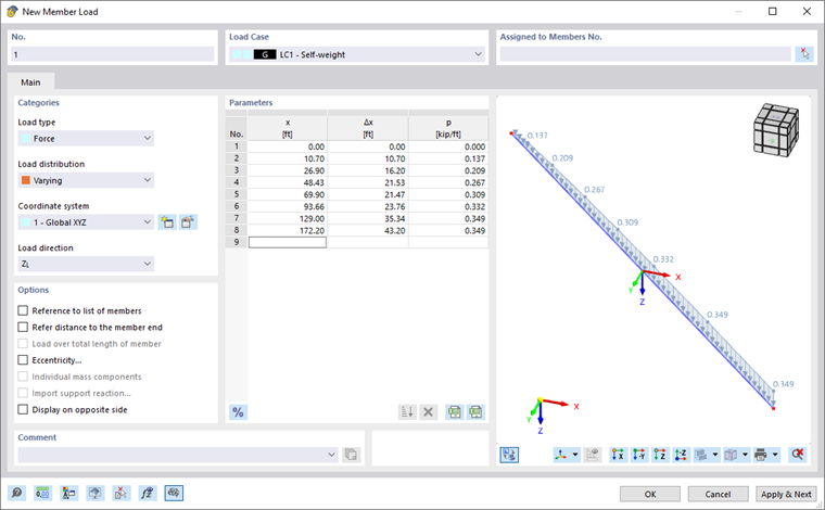
The Main tab manages the basic load parameters.
Categories
The following options are available in the "Load type" list:
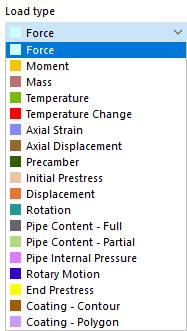
| Load type | Description |
|---|---|
| Force | Concentrated load(s), uniform or variable distributed load |
| Moment | Single moment(s), uniform or variable distributed moment |
| Mass | Mass continuously distributed over member length, which is relevant for Dynamic Analysis. |
| Temperature | Temperature load uniformly distributed (Tt = Tb) or unevenly distributed (Tt ≠ Tb) over the member cross-section |
| Temperature Change | Difference in temperature between the member top and bottom, considering a constant temperature change, if applicable (positive load value: the member's top side heats up) |
| Axial Strain | Imposed or compressive strain ε of the member (positive load value: member is strained) |
| Axial Displacement | Imposed or compressive strain Δl of member |
| Precamber | Imposed curvature of member |
| Initial Prestress | Prestressing force acting on a member before the calculation starts (positive load value: member is strained) |
| Displacement | Imposed displacement by a magnitude Δ for determining influence lines |
| Rotation | Imposed rotation about an angle φ for influence lines |
| Pipe Content – Full | Distributed load due to complete filling of a pipe |
| Pipe Content – Partial | Distributed load due to partial filling of a pipe |
| Pipe Internal Pressure | Uniform internal pressure of a pipe |
| Rotary Motion | Centrifugal force from the mass and angular velocity ω on the member |
| End Prestress | Prestressing force that should be available in the member after the calculation with an iterative determination (positive load value: the member is in tension) |
| Coating – Contour | Force due to the weight of a material with a specific thickness at the cross-section outline (ice, paint) |
| Coating – Polygon | Force due to the weight of a material that encloses the cross-section in a freely definable area (fire protection cladding) |
| Form-Finding (only for the Form-Finding add-on) | Uniform force or geometric specification for the form-finding load (see the chapter Form-Finding Loads) |
The load type and the effects of the signs are illustrated in the upper dialog graphic.
The "Load distribution" list provides various options for displaying the arrangement of the load.
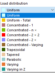
The load distribution scheme is illustrated in the upper dialog graphic. In the "Parameters" dialog section, you can then specify the values, distances, and other parameters of the load.
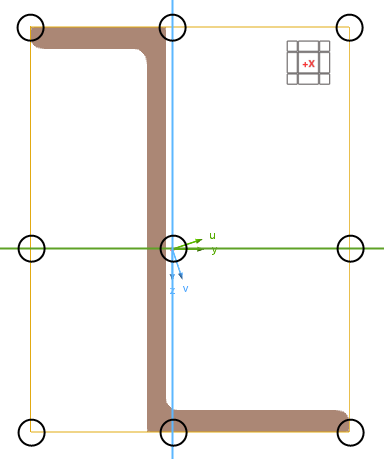
In the "Coordinate system" list, define whether the load acts in the direction of the local xyz-member axes, the local principal axes xuv, or the global XYZ-axes. Alternatively, you can select a user-defined coordinate system or create a new one.
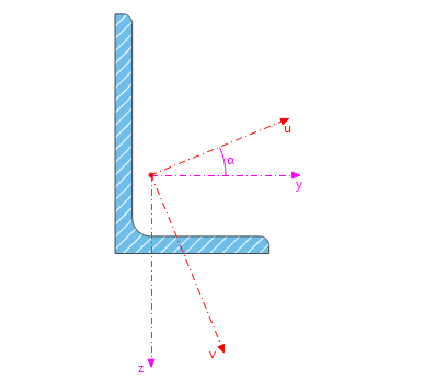
The local x-axis represents the longitudinal axis of the member. In the case of a symmetrical cross-section, the y-axis is the "major" axis of the member cross-section; the z-axis is the "minor" axis. In the case of an asymmetrical cross-section, these are the axes u and v.
Select the "Load direction" from the list to define the effect of the load. Depending on the coordinate system, the local member axes x, y, z, the principal axes x, u, v, the global axes X, Y, Z, or the user-defined axes U, V, W are available for selection.
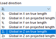
The member load can be related to the true length (such as a weight load) or the projected length (such as a snow load). The load direction is illustrated in the dialog sketch.
Parameters
Specify the load value of the force, moment, or mass. For concentrated or variable loads, several input text boxes are available where you can describe the member load. The meaning of the respective parameters is illustrated in the load sketch.
A positive moment acts clockwise about the corresponding positive axis. The global axes of coordinates in the work window help you to define the sign. For the loads defined locally, you can display the member axes using the
![]() button (see the image Variable Member Load).
button (see the image Variable Member Load).
When defining concentrated or trapezoidal loads, you can use the
![]() button to switch between the relative and absolute entries of distances.
button to switch between the relative and absolute entries of distances.
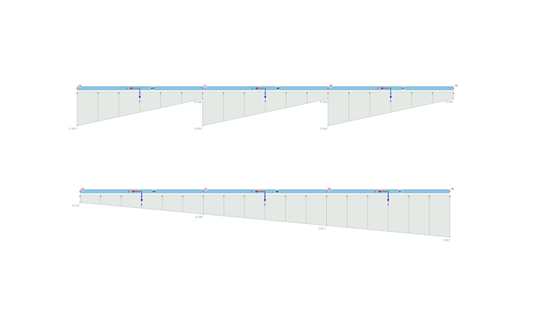
For variable loads, a table is displayed where you can specify the load locations x with the corresponding load values.
Options
Usually, the load acts separately on each of the members that you define in the "Assigned to Members" dialog section. If you tick the "Reference to list of members" check box, the member load acts on the total length of the members: This way, in the case of trapezoidal loads, RFEM does not apply the parameters to each member, but to all members of the list as a whole.
The "Refer distance to the member end" check box is only accessible for loads not acting over the entire length of the member. If you activate it, you can specify the distances in relation to the member end in the "Parameters" dialog section.
When defining trapezoidal loads, you can use the "Load over total length of member" check box to control whether the linearly variable load is arranged continuously from the member start to the member end.
The "Eccentricity" check box is available for the "Force" load type. If selected, you can define an eccentric effect of the member load in the Force Eccentricity tab.
The "Import support reaction" check box allows you to import support forces from another model. Then, you can enter the specifications in another tab (see the image Defining Model, Load, and Line to Import Support Reaction).
You can affect the display of the load vectors by the "Display on opposite side" option.
Force Eccentricity
If the force does not act in the shear center of the cross-section, you can define the location of the load application in the Force Eccentricity tab.
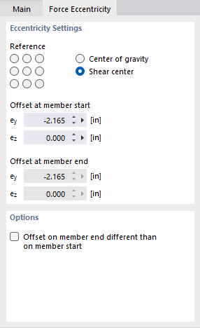
Eccentricity Settings
Nine "Reference" check boxes symbolize distinctive locations on the cross-section. The point in the middle represents the centroid, and the eight edge points represent the intersections of the member axes y and z with the edge lines of a rectangle circumscribing the cross-section. If you activate one of the points, RFEM applies the member load at the corresponding distance from the centroid.
Alternatively, you can apply the load in the "Center of gravity" or in the "Shear center" and define the "Offset at member start" manually in the text boxes below. The distances refer to the local member axes y and z.
Options
If the eccentricity is not uniform along the member, activate the "Offset on member end different than on member start" check box. Then, you can specify the "Offset at member end" in the dialog section above. This way, it is possible to describe a linear distribution of the eccentricity from the member start to the member end.