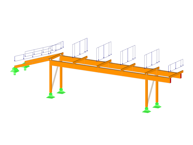
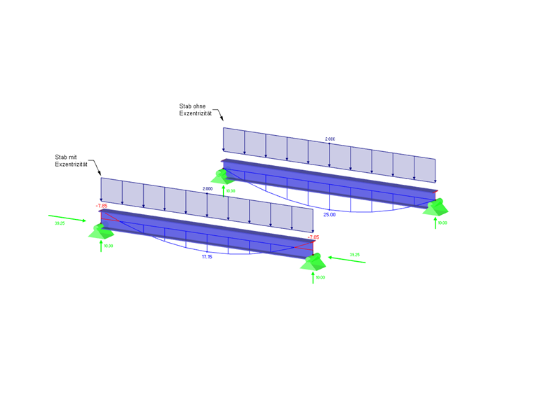
In RFEM, the length of a member corresponds to the distance between two end nodes. Thus, the reality is represented only approximately for cross-section connections or downstand beams. Member eccentricities allow you to connect members eccentrically by means of specific member end sections. Thus, the design moments on horizontal beams may be reduced for frames with large column cross-sections. Member eccentricities are taken into account by a transformation of the degrees of freedom in the local element stiffness matrix.
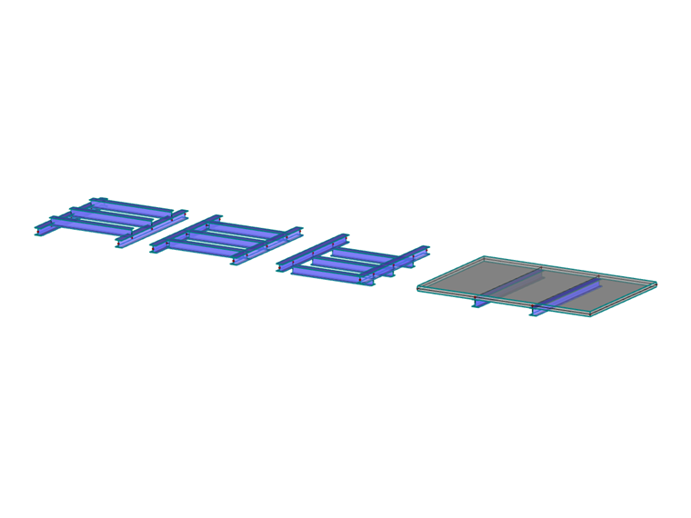
The member eccentricities can be checked in the "Solid Model"
![]() and "Transparent Model"
and "Transparent Model"
![]() display modes.
display modes.
.png?mw=760&hash=177572a2e1120fc2a61cd35dce686890952ddb0d)
Eccentricity Type
You can define the member eccentricity relative to other objects or in absolute values.
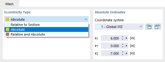
Absolute Ordinates
If the eccentricity type is not defined as "Relative to Section", you can specify the eccentricities in this dialog section (see the image Selecting Eccentricity Type). It is possible to define the local axis system xyz, the global coordinate system XYZ, or a user-defined axis system UVW as reference systems.
Section Alignment
Use the check boxes to define the point of the cross-section where the eccentricity is applied. The cross-section will be moved by this distance to the centroid on the node.
By selecting the point in the middle at the top flange as shown in the image New Member Eccentricity, a horizontal beam is attached with its top edge to a column by a flush connection, for example.
Options
Transverse offset
A transverse offset arranges the member at a certain distance from the cross-section of another member or the thickness of an adjacent surface. After activating the check box, you can define the parameters in the Transverse Offset dialog section.
Axial offset from adjoining member
An axial offset is suitable, for example, to connect a horizontal beam eccentrically to a flange of a column. The distance is determined from the cross-section geometry of the adjoining member. The dialog graphic illustrates the effect of the check box.
Hinge location at node
If there is a hinge at the member end, you can influence the position of the hinge using the check box: If the check box is clear, the hinge is applied to the shifted, eccentric member end. If you tick the check box, the hinge lies directly on the node.
Transverse Offset
In the list of this dialog section, specify the "Object"— a member or a surface—from which the distance is to be determined. Then, enter the number of the member or surface, or select the object graphically with the
![]() button.
button.
Specify the "Axis offset" using the check boxes: The point of the cross-section or surface defines the distance of the member from the object.