A result section creates an intersection plane or line through the model. This allows you to evaluate the results on intersection lines with surfaces and solids.
Use the
![]() button in the toolbar to set result sections directly on the model.
button in the toolbar to set result sections directly on the model.
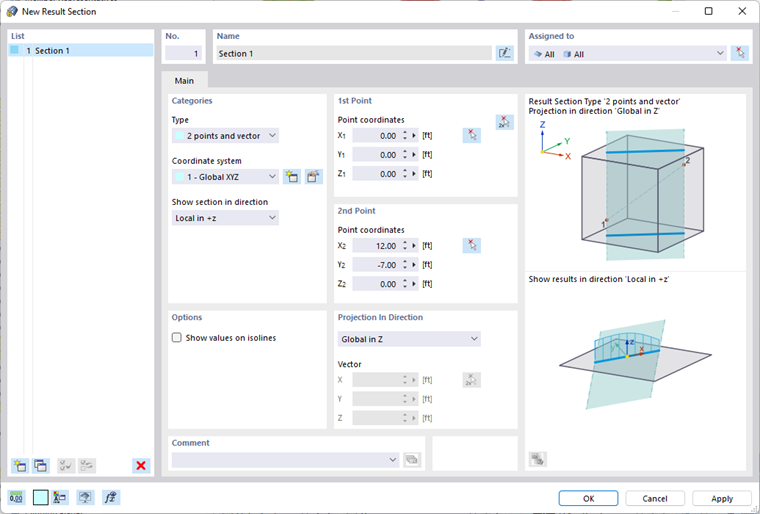
Categories
Define the "Type" of the result section. There are two definition types available in the list:
- 2 points and vector: A section plane is freely placed through the model.
- Line: A cut is made along one or more existing lines.
The sections of the dialog box change depending on the settings.
The result section refers to the global XYZ-"Coordinate system" by default. However, you can also use a user-defined system.
Use the "Show section in direction" list to specify the surface plane in which the section should be displayed.
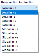
With the default setting "Local in +z", the results are applied at right angles to the surfaces that are affected by the section plane.
1st/2nd Point or Line
Depending on the section type, you can define the two boundary points of the section or the line in these dialog sections.
Enter the "Point coordinates" of the first and second points. You can also use the
![]() button to determine the boundary points graphically. If necessary, adjust the work plane if you want to define any points in the work window rather than nodes.
button to determine the boundary points graphically. If necessary, adjust the work plane if you want to define any points in the work window rather than nodes.
From each of these two points, a straight line is created in the direction of the "projection" (see the dialog section below), defining the intersection plane. If this plane intersects a surface, the result diagram is displayed along the intersection line. If several surfaces are intersected by the plane, the result diagrams are displayed in each of these surfaces. In the "Assigned to" section, you can control which surfaces are affected by the result section.
Options
Select the "Show values on isolines" check box if you want to see the result values at the intersection points of the isolines in the isoline display.
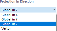
Projection in Direction
The plane of a result section is determined by two points and a projection vector. In addition to the three global projection directions, you can also select a vector in the list to define the third point of the plane according to your requirements.
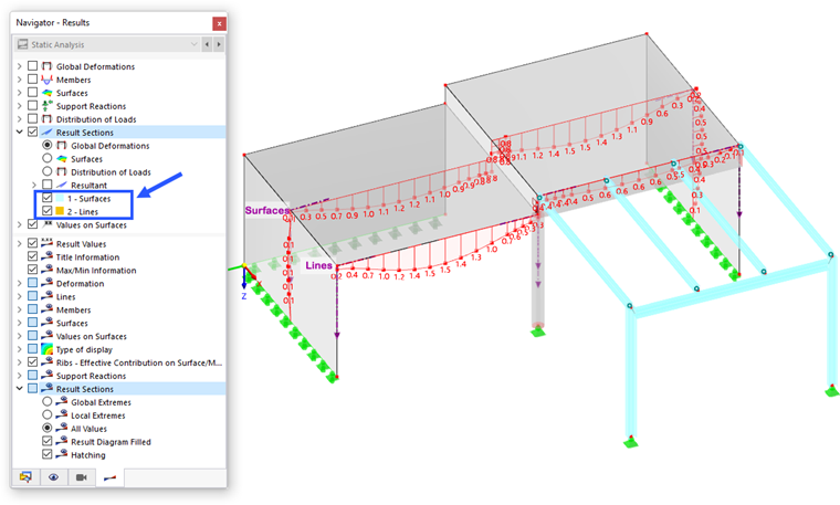
Display of Result Sections
The display of the result sections is controlled in the "Navigator – Results". You can specify there which results and which sections are displayed. The following image shows two result sections: In Section 1, a vertical section plane is placed through the wall and slab surfaces; Section 2 shows the results along two boundary lines.