


You can display the results for members graphically using the Members navigator category. You will find the numerical results of members in the Results by Member table category.
.png?mw=760&hash=4fc3b500e8df248d1d49f11a514acb76ec2ef09a)
Deformations
The image Results by Member in Table shows the table with global member deformations. They refer to the axes X, Y, and Z. The local deformations refer to the axes of the members whose descriptions depend on the specifications set in the Base Data (see the chapter Settings and Options ).
The local member axis system has an impact on the signs of deformations as well: A positive displacement follows the direction of the positive local axis; a positive rotation acts clockwise about the positive member axis.
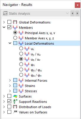
For asymmetrical cross-sections, you can define in the navigator whether the results are related to the principal axes u and v or to the default input axes y and z (see the image Selecting Local Member Deformations in Navigator).
The local displacements and rotations have the following meaning:
| |u| | Absolute value of the total displacement |
| ux | Displacement in the direction of the local x-axis |
| uy | Displacement in the direction of the local y-axis |
| uz | Displacement in the direction of the local z-axis |
| φx | Rotation about the local x-axis |
| φy | Rotation about the local y-axis |
| φz | Rotation about the local z-axis |
The table lists the deformations of each member for the locations defined in the Result Table Manager . There, you can also control which extreme values are displayed.
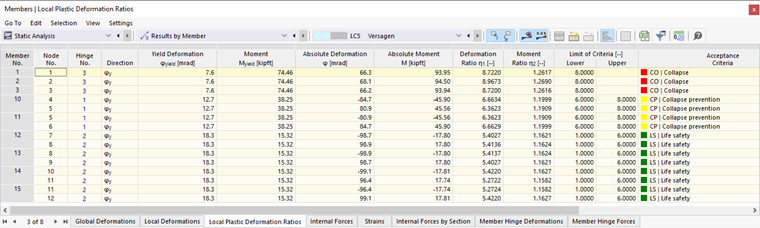
If you have defined a member hinge with plastic properties, the yield deformations, yield internal forces and moments, and acceptance criteria are displayed in the "Local Plastic Deformation Ratios" table.
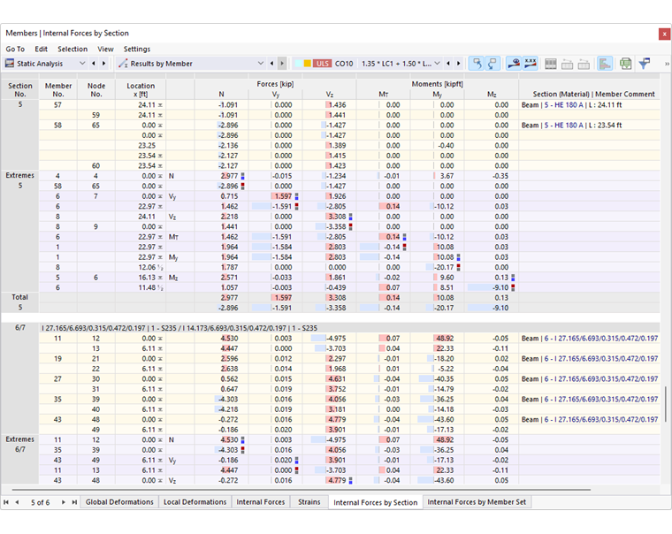
Internal Forces
In the navigator, set the internal forces and moments to be displayed on the members. For asymmetrical cross-sections, you can also choose whether the results are related to the principal axes u and v or to the default input axes y and z (see the image Selecting Local Member Deformations in Navigator). This setting also affects the table output.
The graphical distribution of internal forces is based on the result values available in the FE mesh nodes. They are created according to the specifications in the Mesh Settings dialog box for the members.
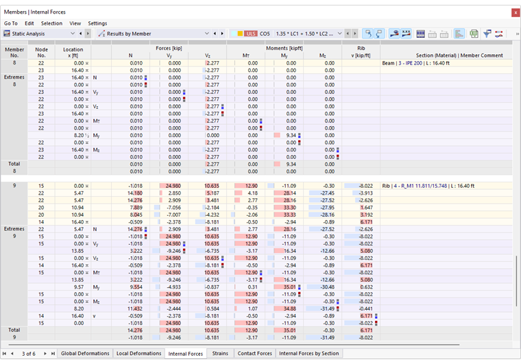
The table lists the internal forces of each member for the locations defined in the Result Table Manager . There, you can also control which extreme values are displayed.
The member internal forces have the following meaning:
| N | Axial force in the direction of the longitudinal axis x of the member |
| Vy | Shear force in the direction of the local y-axis |
| Vz | Shear force in the direction of the local z-axis |
| MT | Torsional moment about the member's longitudinal axis x |
| My | Bending moment about the local y-axis |
| Mz | Bending moment about the local z-axis |
| v | Rib shear force (longitudinal shear force between the plate and the member) |
The local member axis system affects the signs of internal forces.
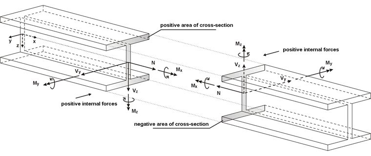
The bending moment My is positive if tensile stresses occur at the positive member face (in the direction of the z-axis). Mz is positive if compressive stresses occur at the positive member face (in the direction of the y-axis). The sign definition for torsional moments, axial forces, and shear forces conforms to the usual conventions: These internal forces are positive if they act on the positive cut face in a positive direction.
The internal forces rule described above only applies if the local member axis z is oriented "downwards" (see the chapter Settings and Options ). However, if the local z-axis is defined "upwards", a positive moment My causes compressive stresses on the positive side of the member, and a positive moment Mz produces tensile stresses.
Further tables of the "Results by Member" category summarize the member internal forces and moments by certain criteria. This way you can see, for example, the extreme values for each cross-section in the "Internal Forces by Section" table.
Strains
.png)
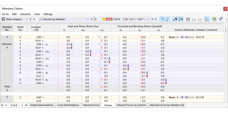
Member strains represent local deformations in the form of axial strains and shearing. According to Hooke's law, they result from the stresses in the members.
The strain tensor for the spatial strain state is described in the chapter Solids . The matrix is simplified for the one-dimensional member element as follows:
The shearing is determined according to the following equations:
The member strains have the following meaning:
| εx | Strain in the direction of the member axis x |
| γxy | Shearing in the direction of the member axis y |
| γxz | Shearing in the direction of the member axis z |
| κx | Curvature about the member axis x |
| κy | Curvature about the member axis y |
| κz | Curvature about the member axis z |
Contact Forces
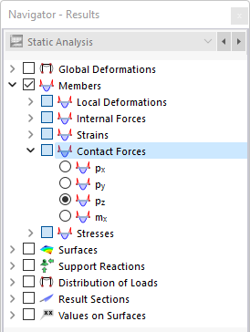
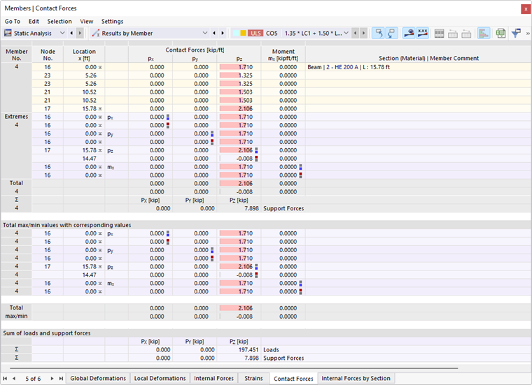
For members with a member support, you can display the "Contact Forces" in the navigator and table.
The contact forces px, py, and pz are effective in the directions of the respective member axes. They are shown in relation to a standard length. For asymmetrical cross-sections, you can define in the navigator whether the results are related to the principal axes u and v or to the default input axes y and z (see the image Selecting Local Member Deformations in Navigator).
The contact moments mx about the member's longitudinal axis are also shown in relation to a standard length.
Sum of Loads and Sum of Support Forces
For load cases and load combinations, the check sums Σ of the loading and support forces are indicated at the end of the table. This balance will show a difference if the model also has nodal supports, line supports, or surface supports. Those support forces should also be considered in the overall balance.
Member Hinge Deformations
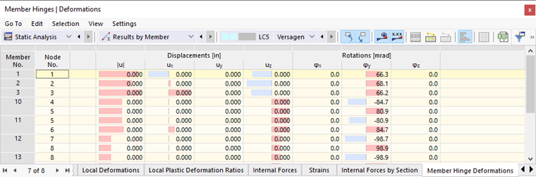
For members with a member hinge, you can display the "Member Hinge Deformations" in the table. They show you the displacements or rotations transferred by each hinge.
Member Hinge Forces
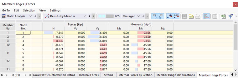
For members with a member hinge, you can display the "Member Hinge Forces" in the table. They show you the forces or moments transferred by each hinge.
Stress
Using the entries of the "Stresses" category, you can graphically display the stress curves of axial stresses, shear stresses, and equivalent stresses on the member cross-sections. This kind of display requires no license for the Stress-Strain Analysis add-on. However, for the enveloping results of result combinations and design situations, it is not possible to show cross-section stresses.
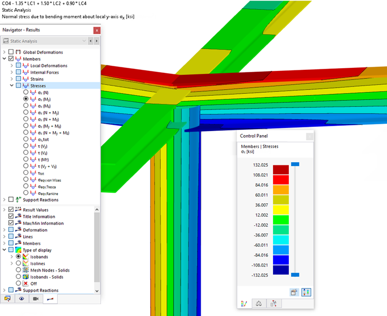
In the "Stresses" category, you can select from various stress components and combinations. This way, you can check, for example, the distribution of tensile and compressive stresses due to bending, which are available on an I-section's flanges. The panel controls the assignment of values. The chapter Control Panel explains how to adjust the colors and values.
The stresses are determined using an FEA calculation based on the internal forces and cross-section properties.