Solid loads are forces, temperature effects, strains, buoyancy loads, or rotary motions that act on solids.
In the list, select the "Load Case" to which you want to assign the load.
Categories
The following options are available in the "Load type" list:
| Load type | Description |
|---|---|
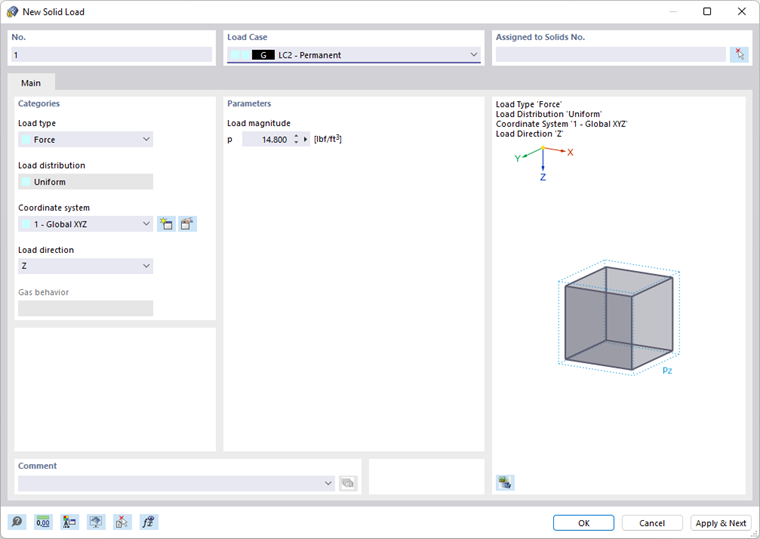
| Force | Solid load acting uniformly in one of the global directions |
| Temperature | Uniform or linearly variable temperature change in solid (positive load value: solid heats up) |
| Strain | Uniform or linearly variable imposed or compressive strain ε of solid (positive load value: solid is strained) |
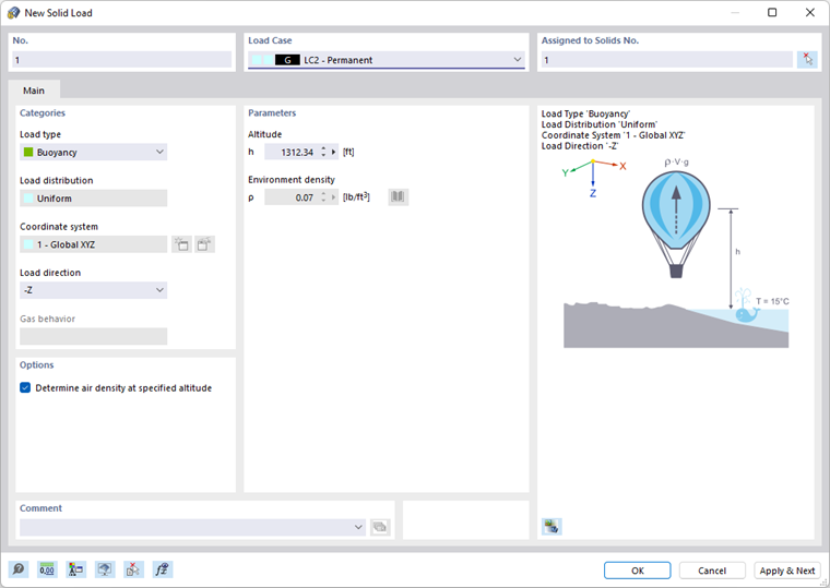
| Buoyancy | Weight of displaced material whose density can be entered or selected from a library using the
|
| Rotary Motion | Centrifugal force from mass and angular velocity ω on solid |
| Gas (only for the Form-Finding add-on | Overpressure for form-finding load (see the chapter Form-Finding Loads of the Form-Finding manual). |
The load type as well as the effect of the signs are illustrated in the dialog graphic.
The "Load distribution" list provides several options for temperature loads and strains to display the effect of the load.
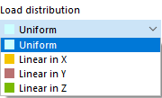
The load distribution scheme is illustrated in the dialog graphic. In the "Parameters" dialog section, you can then specify the load values and reference nodes.
Solid loads in the global "Coordinate system" act in the direction of a global axis: X, Y, or Z. Alternatively, you can select a user-defined coordinate system or create a new one.
Select the "Load direction" from the list to define the effect of the load. Depending on the coordinate system, the global axes X, Y, Z or the user-defined axes U, V, W are available for selection.
The "Gas behavior" section is accessible if the Form-Finding analysis add-on is activated (a license is required).
Parameters
Specify the load magnitude of the force, temperature, strain, or rotary motion. For buoyancy loads, you can define the environment density ρ (see the image Determining Air Density). For linearly variable loads, several input text boxes are available where you can describe the solid load. The meaning of the respective parameters is illustrated in the load sketch.
Options
This dialog section is only displayed for the "Buoyancy" load type. If you activate the "Determine air density at specified altitude" check box, you can have the environment density ρ determined from the altitude by the program.