


A free rectangular load acts as a uniform or linearly variable surface load on a rectangular, freely definable zone of a surface.
In the list, select the "Load Case" to which you want to assign the load.
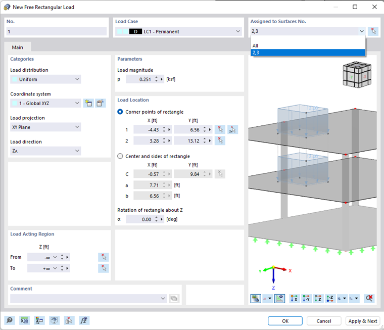
In the "Assigned to Surfaces" dialog section, you can control the effect of the rectangular load. Several options are available for selection in the list (see the image New Free Rectangular Load):
- "Empty": The load does not act on any surfaces.
- All: The load is applied to all surfaces that are cut perpendicular to the projection plane, starting from the load locations.
- "Number": The load acts only on the surfaces of the specified numbers.
Main
The Main tab manages the basic load parameters.
Categories
The following options are available for selection in the "Load distribution" list:
- Uniform: The rectangular load acts with a constant magnitude.
- Linear in X / Y / Z: The load has a linearly variable magnitude in the direction of a global axis.
- Varying in Z: The load acts with a magnitude that is variable in the Z-direction, which you can freely describe in the Varying in Z-direction tab in a table.
- Varying Along Perimeter: The load acts with a variable magnitude along the perimeter, which you can freely describe in the Varying Along Perimeter tab in a table.
- Varying in Z and Perimeter: The load acts along the perimeter with a magnitude varying in the Z-direction, which you can freely describe in the Varying in Z-Direction and Varying Along Perimeter tabs.
If the rectangular load does not refer to the global "Coordinate system" XYZ, you can select a user-defined coordinate system or create a new one.
In the "Load projection" list, select on which of the global planes (XY, YZ, or XZ) you want to project the load. From the load location points, RFEM "constructs" some straight lines perpendicular to this projection plane. The definition points of the rectangular load result from the intersection points of these straight lines with the surfaces.
Select the "Load direction" from the list to define the effect of the load. Depending on the coordinate system, the local surface axes x, y, z, the global axes X, Y, Z, or the user-defined axes U, V, W are available for selection.

The self-weight of an object represents a load acting on the true area. A snow load, however, refers to the projected area.
Parameters
Specify the "Load magnitude" of the force. For a linearly variable load, you have to enter two load values.
Load Location
You have two options to define the dimensions of a rectangular load:
- Define the "Corner points of rectangle" by entering the corresponding coordinates. You can also use the
 button to define both points graphically.
- Specify the "Center and sides of rectangle" by defining the center point C as well as the side lengths a and b.
If necessary, you can provoke a "Rotation of rectangle about Z". A positive angle α rotates the rectangular load clockwise about the positive axis.
Load Acting Region
As described above, the load acts on the surfaces that are cut perpendicular to the projection plane, starting from the load location. If you have selected the "All" option in the Assigned to Surfaces dialog section, you can limit the effect of the load by means of geometric criteria.
By default, the load acts indefinitely in the interval from -∞ to +∞. You can use the "From" and "To" text boxes to reduce the load effect to certain zones.
Varying in Z-Direction
The Varying in Z-direction tab is available for the "Varying in Z" and "Varying in Z and Perimeter" load types.
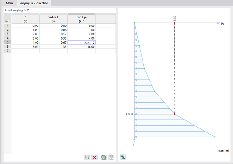
Here, you can describe the Z-ordinates with the corresponding load values in a table.
Varying Along Perimeter
The Varying Along Perimeter tab is available for the "Varying Along Perimeter" and "Varying in Z and Perimeter" load types.
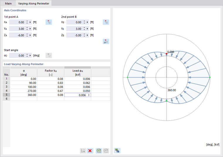
Enter the "Axis Coordinates" of two points to define the initial position of the load. You can define the points graphically with the
![]() button. In the "Load Varying Along Perimeter" dialog section, you can then describe the angles α with the corresponding load values in a table.
button. In the "Load Varying Along Perimeter" dialog section, you can then describe the angles α with the corresponding load values in a table.