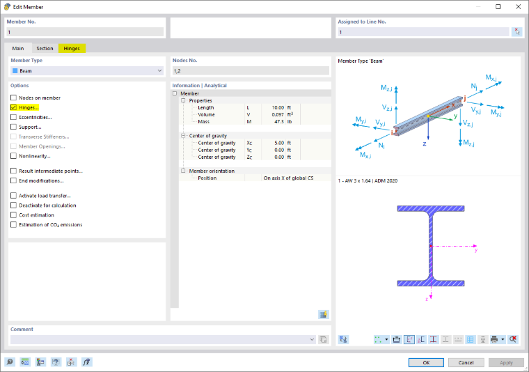
The Main tab manages the basic member parameters. When you select a check box in the "Options" dialog section, another dialog tab is usually added. You can specify the details there.
Member Type
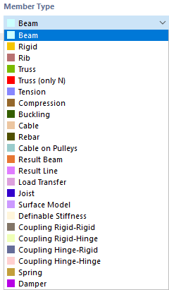
The member type controls the way internal forces and moments can be absorbed, or which properties are required for the member. Various member types are available for selection in the list.
Beam
A beam is a bending-resistant member that can transfer all internal forces and moments. A beam member has no hinges at its member ends. This member type can be stressed by all types of loads.
Rigid
A rigid member couples the displacements of two nodes by means of a rigid connection. Therefore, this member corresponds in principle to a coupling. This allows you to define members with a very high stiffness while taking into account hinges, which can also have spring constants and nonlinearities. Hardly any numeric problems occur, as the stiffnesses are adjusted to the system.
Internal forces for rigid members are displayed if you activate the results for couplings in the Navigator – Results in the "Members" category at the bottom.
The following stiffnesses are applied for rigid members:
| Longitudinal stiffness E · A | 1013 · ℓ [SI unit] where ℓ = member length |
| Torsional stiffness G · IT | 1013 · ℓ [SI unit] |
| Bending stiffness E · I | 1013 · ℓ3 [SI unit] |
| Shear stiffness GAy / GAz (if activated) | 1016 · ℓ3 [SI unit] |
Rib
Ribs can be used to model T-beams (downstand beams). The eccentricities and effective beam widths are taken into account in the FEM model for this member type.
Ribs are primarily suitable for reinforced concrete members, as the rib internal forces and moments as well as the rib cross-sections are taken into account in the concrete design. A steel plate with a welded "rib" should be modeled as a surface with an eccentrically connected member.

The "Rib Alignment" list provides several options.

Generally, a rib is a member that is eccentrically arranged. The eccentricity is determined automatically from half the surface thickness and half the member height. However, it can also be defined manually. The stiffness of the model is increased due to the eccentricity of the rib. In the case of a centric arrangement, the centroidal axis of the rib lies in the center of the surface.
The effective widths of the rib need to be defined in the "Flange Dimensions" section for the left and right sides. In most cases, you can keep the "Autodetect" setting that the program uses to determine the two surfaces. If more than two surfaces adjoin each other along the line of the rib member, the governing surfaces must be defined manually.
There are various options for entering the integration widths b-y,int and b+y,int (see the image New Rib): The widths can be entered directly or determined automatically from the member length with the options Lref / 6 and Lref / 8. They can also be determined according to the specifications of a standard, for example according to "EC2", Section 5.3.2.1.
The by,int values define the width of the surface or the catchment area from which the internal forces are to be integrated. The by,eff values represent the cross-section width of the rib flange from the center of the web to the respective edge. By default, by,int and by,eff are set to the same value. However, you can define them separately by clicking the
 button.
If nodes of the "Node on Member" type have been defined, the rib can be defined in sections for the individual segments. If several segments are defined, the shifting width ranges can be connected to each other in a linearized manner via the "Linear Distribution" table column to prevent large stiffness changes in the rib member.
In the case of 3D models, the effective widths have no influence on the stiffness because the increased stiffness is taken into account by the eccentric member. However, the effective widths affect the distribution of the internal forces and moments of members and surfaces.
Truss
A truss member corresponds to a beam member with moment hinges at both ends. In addition, the rotation about the longitudinal axis at the member start is released by a hinge φx. For this member type, bending and torsional moments from the member's loading are displayed.
Truss (only N)
This truss type with the stiffness E ⋅ A is able to absorb normal forces in the form of tension and compression. RFEM shows only nodal internal forces and moments. The member has a linear distribution of internal forces provided that there is no concentrated load acting on the member. RFEM shows no moment distribution that may arise due to self-weight or a line load. The nodal forces, however, are calculated from the member loads, which guarantees correct transmission.
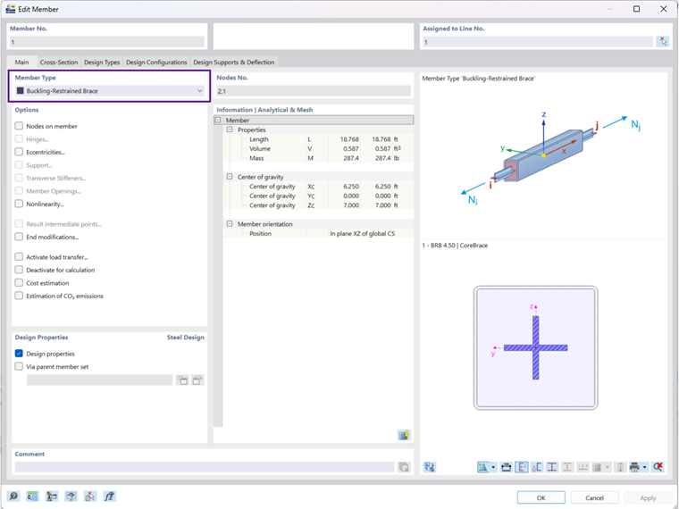
Buckling-Restrained Brace
The Buckling-restrained brace type allows for the modeling of a member with a steel core (flat bar or cross-shaped cross-section) and a concrete-filled coating in a square or round hollow section. It is used in particular in the U.S. for stiffening buildings at risk of earthquake damage.
The steel core moves freely within the concrete coating without any bond. Under compressive loading, “micro-buckling” occurs with high mode shapes, since the coating prevents global buckling of the entire member.
Only the steel core is considered for the member’s stiffness; for the automatic self-weight, the concrete coating with the outer steel shell is also included.
Tension
A tension member can only absorb tensile forces. The member type corresponds to a "Truss (only N)" member, which fails in the case of a compressive force.
A frame structure including tension members is calculated iteratively: In the first step, the internal forces and moments of all members are determined. If tension members get a negative normal force (compression), another iteration step starts. The stiffness components of these members are no longer considered—they have failed. This process continues until no other tension member fails. A system can become unstable due to the failure of tension members.
Compression
A compression member can only absorb compressive forces. The member type corresponds to a "Truss (only N)" member, which fails in the case of a tensile force. Failing compression members can lead to an unstable system.
Buckling
A buckling member corresponds to a "Truss (only N)" member, which absorbs tensile forces without limitation, but compressive forces only until the critical force is reached. This force is determined as follows for the Euler buckling mode 2:
With this type of member, you can often avoid instabilities that occur in nonlinear calculations performed according to second-order theory or large deformation analysis due to buckling of truss members. If you replace them (realistically) by buckling members, the critical load is increased in many cases.
Cable
Cables only absorb tension forces. Thus, any chain of cables can be determined by an iterative calculation according to the large deformation analysis considering longitudinal and transversal forces.
Cables are suitable for models where large deformations may occur with the corresponding changes of internal forces and moments. For simple guying like for a roof canopy, tension members are completely sufficient.
Rebar
This member type can be used to model flexible steel reinforcement in the FE model of a reinforced concrete element. For example, discontinuity areas can be analyzed based on the truss analogy (tension and compression struts in cantilevers, beams with openings).
The rebar has an automatic connection function to other elements, such as members or surfaces, if it is physically located within the element. Like the Truss (only N), a rebar only has a tangent stiffness. Nonlinear material behavior is currently not yet possible.

In the “Settings” section, a flexible reinforcement is set as the member type. Other rebar types are available if the Tendons add-on is activated.
In the “Master Objects” section, assign the members or surfaces in which the rebar is located. To do this, use the
 button. You can then use the
 button to automatically connect the rebar to the master object.
Cable on Pulleys
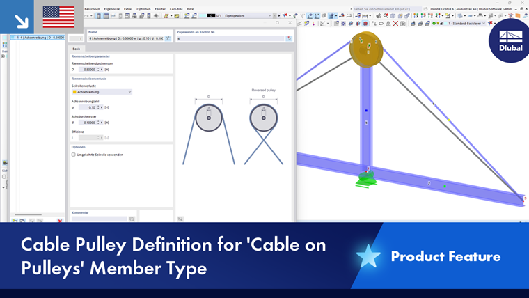
This cable type only absorbs tensile forces and is calculated according to the cable theory (large deformation analysis). However, a cable member on pulleys can only be defined on a polyline that lies in a plane and has at least three nodes. This type of member is, therefore, suitable for flexible tension elements whose longitudinal forces are transferred through the model via deflection points. One application example is a pulley block.
In contrast to a normal cable member, displacement is only possible in the internal nodes in the longitudinal direction (ux). The member must therefore not be subjected to member loads that act in the local y- or z-direction. Only displacements ux and axial forces N are taken into account.
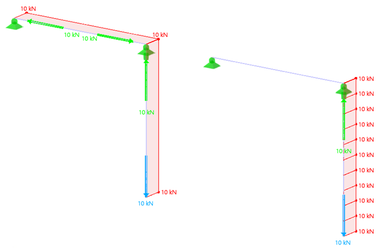
At the internal nodes of the polyline, it is not important whether there is a nodal support or the member is connected to another structure: Because the global system of the cable member is analyzed over the length of the polyline.
In the “Cable Pulleys” tab, you can define additional parameters, such as deflection nodes and pulley wheel properties. Nodes, cables, and rigid members are generated based on these specifications.
Result Beam
Result beams are suitable for integrating surface, solid, or member results in a fictitious member. This allows you to read off, for example, the resulting shear forces of a surface for the masonry design.
The line of a result beam can be placed anywhere in the model. It requires neither a support nor a connection to the model. However, it is necessary to assign a cross-section to enable the design. It is impossible to apply loads to a result beam.
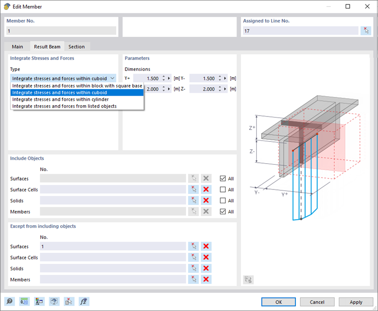
In the "Integrate Stresses and Forces" dialog section, select the result beam type to define the geometric shape of the integration area. Then, in the "Parameters" dialog box section, you define the dimensions. They are related to the line of the member in its centroid.
In the "Include Objects" dialog section, specify the surfaces, surface cells, solids, and members whose results are to be taken into account in the integration. Alternatively, select "All" objects and then exclude certain elements in the "Except from including objects" section.
Result Line
Result lines are suitable for integrating surface, solid, or member results in a line. This line can be placed anywhere in the model.
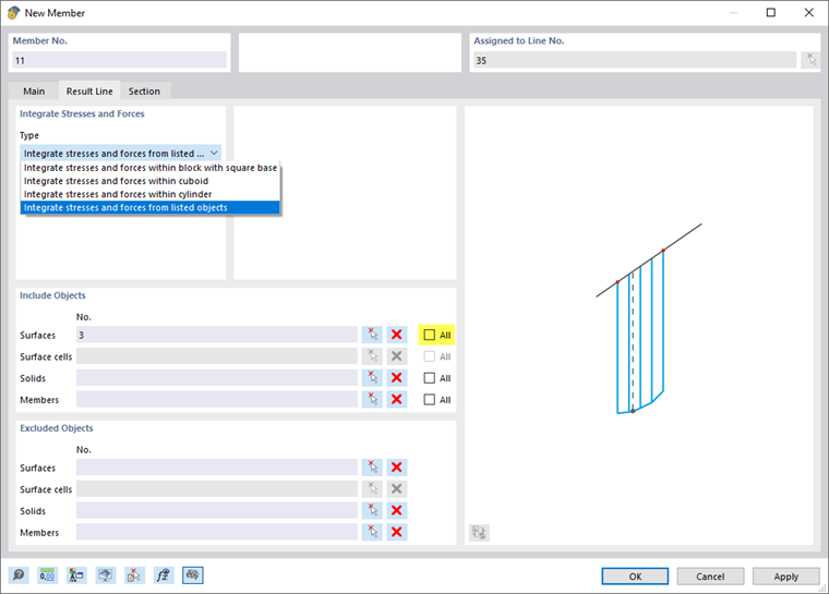
The principle corresponds to a result beam. However, you do not need to assign a cross-section. In the 'Section' tab, you can view the length of the line and, if necessary, rotate the line for the result display; it has no further function.
Load Transfer
This member type can be used to apply loads to objects that are connected to the member at the end or intermediate nodes. The member itself has no stiffness. You can define the criteria for load transfer in a new tab.
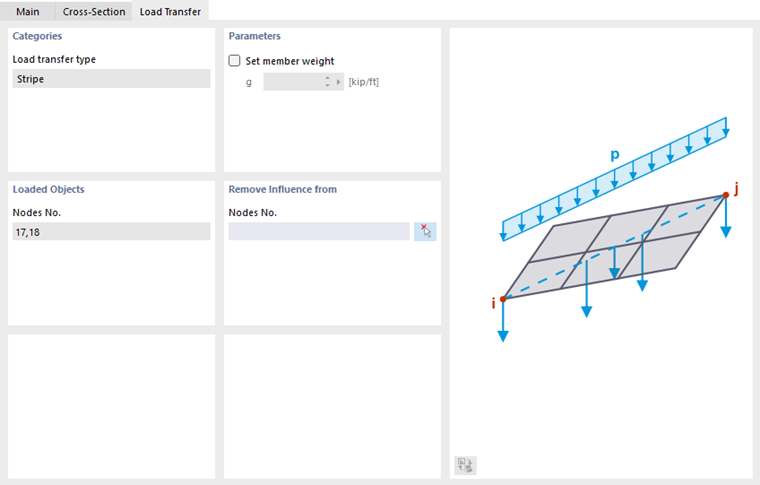
The load is currently transferred using the strip method. The load on the load transfer member—a member load or a nodal load of the Force, Moment, or Mass type—is transferred proportionally to the nearest common structural objects. These are, for example, supported nodes, members, nodes of surfaces, or supported lines.
If the self-weight of the member is to be taken into account, you can define the member weight in the “Parameters” section.
In the “Loaded Objects” section, the numbers of the nodes at which the member load is transferred to the subsequent objects are specified. If not all of these nodes are relevant, you can exclude certain nodes in the “No effect on” section.
Joist
This member type makes it possible to apply the cross-section properties for Open Web Steel Joists that the Steel Joist Institute has defined in Virtual Joist tables. These Virtual Joist sections represent equivalent wide-flange beams which closely approximate the joist chord area, the effective moment of inertia, and the weight. Thus, the beam is replaced by a member with a virtual cross-section. This allows complex load-bearing units, such as a truss girder, to be simulated in the overall system.
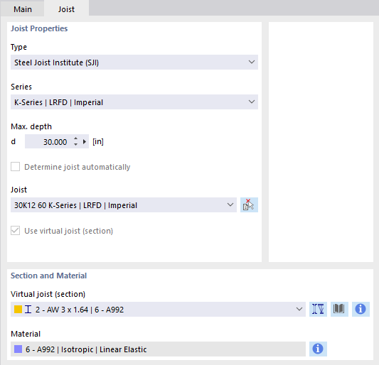
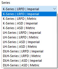
Select the "Series" of the virtual joist in the list.
Then, you can define the exact type in the "Joist" list below.
The
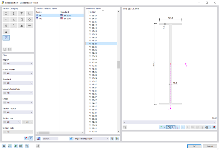
 button in the "Section and Material" section allows you to import the virtual joist from the section library.
Surface Model
This member type is primarily suitable for representing castellated beams or cross-section reductions such as holes or openings for supply lines in the member model. The relevant member is converted into a surface model where the member openings are arranged by user specification. However, the member is maintained. The following requirements must be met:
- The cross-section represents a standardized or parametrized thin-walled section with a web.
- The material of the cross-section is based on an isotropic linear-elastic material model.
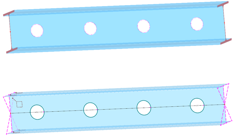
Using the "Surface Model" member type, the member is available as both a member and a surface object. The geometrical properties are identical; both models have the same centroid. The display can be controlled in the Display Navigator via Model → Basic Objects → Members → Surface Model, or with the
 button in the toolbar.
The FE mesh of the surface model is generated automatically; currently it cannot be influenced. When performing structural analyses, the surface model is used. Then, both the member results (like for a result beam where the stresses of the member's sub-surfaces are integrated in member internal forces) and the surface results are available for evaluation. Again, data can be controlled here via the Navigator - Display or the
button.
In the add-ons, designing a member of the surface model type is carried out with the member internal forces and the member cross-section.
As can be seen in the image above, several rigid members are generated at the member ends of a surface model member. They connect the surface model with the end nodes of the adjacent members. This way, the correct transfer of the internal forces and moments to the 1D objects is ensured. If several surface model members are connected to one another, these coupling members are generated for each member.
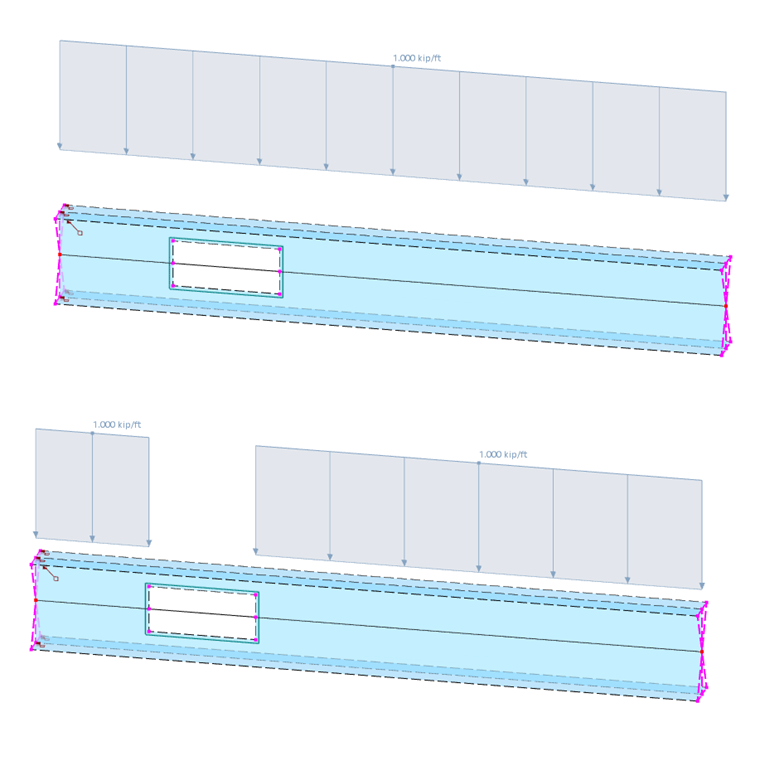
In this case, define a force eccentricity at the cross-section for the member load. In this way, the load is applied realistically to the cross-section edge and also maintained in the surface model.
Definable Stiffness
This member type allows you to use a member with user-defined stiffnesses. The stiffness properties have to be defined in the "New Member Definable Stiffness" dialog box (see the chapter Member Definable Stiffnesses).
Coupling
A coupling member is a virtual, very stiff member with rigid or hinged member ends. There are four options for coupling the degrees of freedom for the start and end nodes, combining the "Rigid" and "Hinge" settings. Couplings can be used to model special situations for the transfer of forces and moments. The normal and shear forces or torsional and bending moments are transferred directly from node to node.
Spring
A spring member offers the possibility to display linear or nonlinear spring properties by definable effective areas. For a spring member, you only need to define the member length Lz in the "Section" tab, but no cross-section: The stiffness of the member results from the spring parameters that you define in the "New Member Spring" dialog box (see the chapter Member Springs).
Damper
In principle, a damper corresponds to a spring member with the additional property "Damping coefficient". This member type extends the possibilities for dynamic analyses according to the Time History Analysis.

As for a spring member, you only need to define the member length Lz in the "Section" tab, but no cross-section: The stiffness of the member results from the spring parameters that you define in the "New Member Spring" dialog box (see the chapter Member Springs). You can control the damping properties by means of the damping coefficient X.
Options
In this dialog section, you can use the check boxes to define further member properties.
Nodes on Member
With one or more nodes on the member, you can split the member into segments without dividing the member (see chapter Nodes).
Hinges
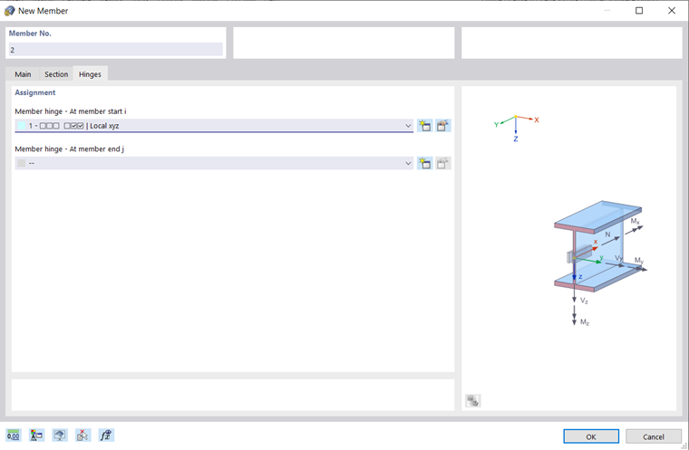
You can arrange hinges on a member to control the transfer of internal forces and moments at the end nodes (see the chapter Member Hinges). The input is blocked for specific member types because internal hinges are already available. You can assign hinges separately "At member start i" and "At member end j".
Eccentricities
Eccentricities allow you to connect the member eccentrically at the end nodes (see the chapter Member Eccentricities). You can assign eccentricities separately "At member start i" and "At member end j".
Support
You can assign a support to the member that is effective along its entire length. The degrees of freedom and spring constants have to be defined under the support conditions (see the chapter Member Supports).
Transverse Stiffeners
Transverse stiffeners applied to the member have an influence on the warping stiffness of the member. They affect the calculation using warping torsion, taking into account seven degrees of freedom (see the chapter Member Transverse Stiffeners).
Member Openings
Member openings affect the cross-section properties and the distribution of internal forces and moments. They are relevant for the "Surface Model" member type. The chapter Member Openings describes how you can define the type and position of the openings.
Nonlinearity
You can assign a nonlinearity to the member. The nonlinear properties have to be defined as member nonlinearities (see the chapter Member Nonlinearities).
Result Intermediate Points
By applying result intermediate points, you can control the table output of results given along the member. The division points have to be defined in the "New Member Result Intermediate Point" dialog box (see the chapter Member Result Intermediate Points).
End Modifications
By setting end modifications, you can graphically adjust the geometry of the member at its ends. This way, you can prepare projections, reductions, or bevels for the rendered display.
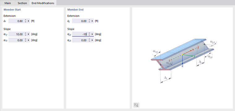
"Extension": You can define an "Extension" for the member start and end. A negative value Δ acts as a shortening.
"Slope": You can bevel any member end by a slope. It is possible to enter inclination angles about the two member axes y and z. A positive angle causes a clockwise rotation about the respective positive axis.
Activate Load Transfer
The check box allows you to distribute the load on the member–regardless of the stiffness of the member–using a load transfer. This means that the member is effective in the model due to its stiffness. The distribution of the load to the neighboring objects, on the other hand, is controlled by the parameters that you can define in the Load Transfer tab.
Deactivate for Calculation
If you tick this check box, the member including loading will not be considered in the calculation. This way, you can analyze the structural behavior of the model; how it changes if certain members are not effective. It is not necessary to delete these members; their loading is kept as well.
Cost Estimation
The cost estimation is typically based on the costs of the materials assigned to the members of a cross-section (see the chapter Materials). If specific parameters are to apply to a member, you can define the unit costs and units separately in the “Cost Estimation” tab. The principle corresponds to the procedure described for Sections.
Estimation of CO₂ Emissions
The estimation of CO₂ emissions is also generally based on the cross-section’s material. However, you can also specify the unit emissions and units for each member individually in the “CO₂ Emissions Estimation” tab. The principle is described in the chapter “Sections” for the emissions of specific cross-sections.