


In the Settings & Options tab, you can adjust the value for the acceleration of gravity, the geometric tolerances of objects, and the alignment of axes, as well as configure settings for automatically connecting objects and calculating costs.

Settings
In this section, you can check the value of the "Gravitational acceleration" g. It is used to determine the self-weight of members and surfaces, to convert masses (“mass conversion constant”) and for dynamic analyses. The default value is 10.00 m/s², which you can adjust, if necessary.
The “North Orientation” describes the location of the model in relation to the main compass direction. A north orientation of 0° is preset, which corresponds to a north orientation along the global X-axis. If you want to change the orientation of the model, select the check box and enter the angle Φ.
Model Tolerances
When modeling or importing data from a CAD program, slight geometric differences may occur in the model objects. RFEM corrects these inconsistencies automatically if particular distances are exceeded. Thus, nodes located very close to each other will be combined, lines or members located outside of planes will be integrated into surfaces, or minimally inclined lines and members will be classified as vertical.
The preset tolerances are suitable for most models. In the case of small model dimensions, it may be necessary to adjust the tolerances accordingly.
Options
The options in this section control whether "representatives" for members and sets of members or "surface cells" are used in the model.
If activating the check boxes for "Member Representatives" and "Member Set Representatives", the additional tabs Member Representatives and Member Set Representatives are available in the dialog box. If you select the "Surface Cells" check box, the program automatically detects closed partial areas of surfaces. This object type is described in the chapter Surface Cells.
The “Activate Rule-Based Link Generator” list opens the option to use a generator to link unconnected model objects. This feature is described in the chapter Rule-Based Link Generator . Use the
![]() button to create a new generator and the
button to create a new generator and the
![]() button to edit the entry selected in the list.
button to edit the entry selected in the list.
Global Axes XYZ
This dialog section controls the orientation of the global axis Z. The Z-axis is usually directed upwards in CAD programs, and downwards in structural analysis programs. This is irrelevant to the calculation.
If Z is directed upwards, the factor −1.0 is automatically applied in Z for the "Active self-weight" function in the load case (see the chapter Load Cases ).
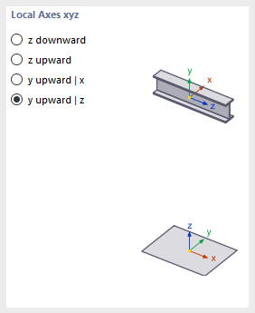
Local Axes xyz
The descriptions of the member axes are regulated differently in the standards. In this dialog section, you can define how the principal member axes z or y, as well as the surface axis z, are oriented in order to adapt the local axis systems to the regional conventions.
The positions of the local member and surface axes are illustrated in the dialog graphics.
Cost / CO₂ Emission Estimation
The costs and CO₂ emissions of a model are determined based on the members, surfaces, and solid elements of the model. This is done using a method similar to that used in practice to calculate the total cost of a building. The model is divided into units, such as basement ceiling, exterior wall, or downstand beam. Specific unit costs are developed for these units, covering all costs to be recorded (price per surface, price per length, price per weight). The quantities of the individual units (weight, volume, surface) are then multiplied by the corresponding unit costs. This yields the partial costs for each unit. The sum of all partial costs yields the total cost of the model. The estimation of CO₂ emissions is based on the same approach.
Specify the currency symbol for the costs. You can then define the cost per unit for the materials and objects.
The adjustment factors allow for scaling of the costs and CO₂ emissions of the model globally. This can be useful for adjusting costs during the progress of the project.