


Materials are required for the definition of surfaces, cross-sections, and solids. The material properties are incorporated into the stiffnesses of these objects.
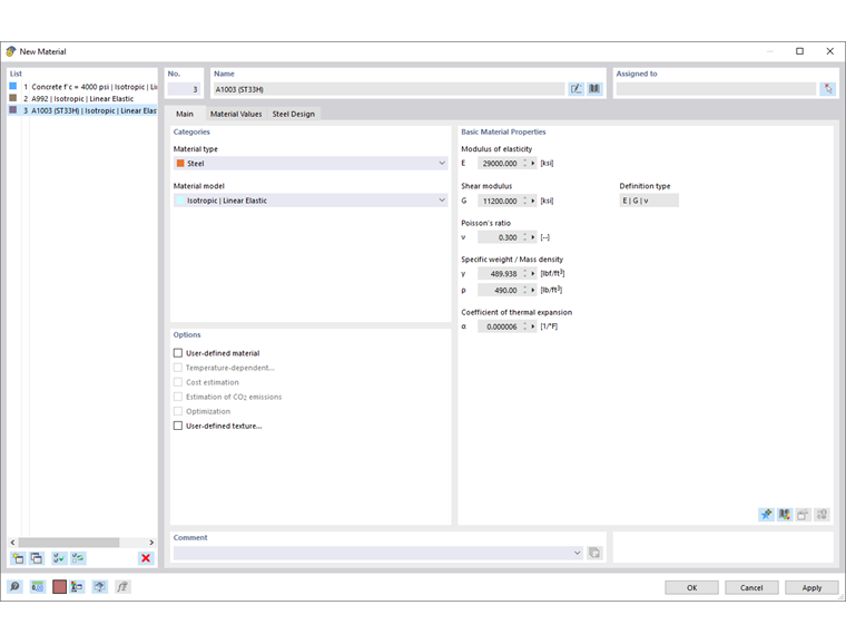
Name
You can define any name for the material. If the designation matches an entry in the library, RFEM reads in the stored material properties. To select the material in the library, click the button
 at the end of the input line. The import of materials is described in the chapter Material Library.
For materials from the library, the 'Basic Material Properties' are firmly set and cannot be changed. If you want to use user-defined properties of the material, activate the User-Defined Material check box in the 'Options' section (see section User-Defined Material).
Base
The Base tab manages the basic material parameters. It also provides control options for special properties that you can define in additional tabs.
Categories
In this section, you define the material type and the material model.
Material Type
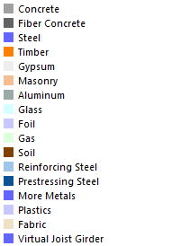
The material type controls which parameters and coefficients are relevant for the design. This classification also specifies the partial safety factors of the material, which are taken into account in the design depending on the standard.
For a material from the library, one of the following material types is preset.
Material Model
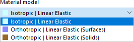
The following material models are available for selection in the list:
- banner.text
Isotropic | Linear Elastic
The linear elastic stiffness properties of the material are independent of the direction. They can be described as follows:
|
E |
Modulus of elasticity |
|
G |
Shear modulus |
|
ν |
Poisson's ratio |
The following conditions apply:
- E > 0
- G > 0
- -1 < ν ≤ 0.5 (for surfaces and solids; for members unlimited upwards)
The elasticity matrix (inverse of the stiffness matrix) for surfaces is:
Orthotropic | Linear Elastic (Surfaces)
With this material model, stiffness properties can be defined that differ in the two surface directions x and y. This allows, for example, the properties of glass-fibre reinforced plastic, ribbed slabs, or the stress directions of reinforced slabs to be modeled. The surface axes x and y are perpendicular to each other in the surface plane.
To define different material properties for the x- and y-directions, activate the User-Defined Material check box in the 'Options' section. In the Orthotropic | Linear Elastic (Surfaces) tab, you can then define the parameters of the material.
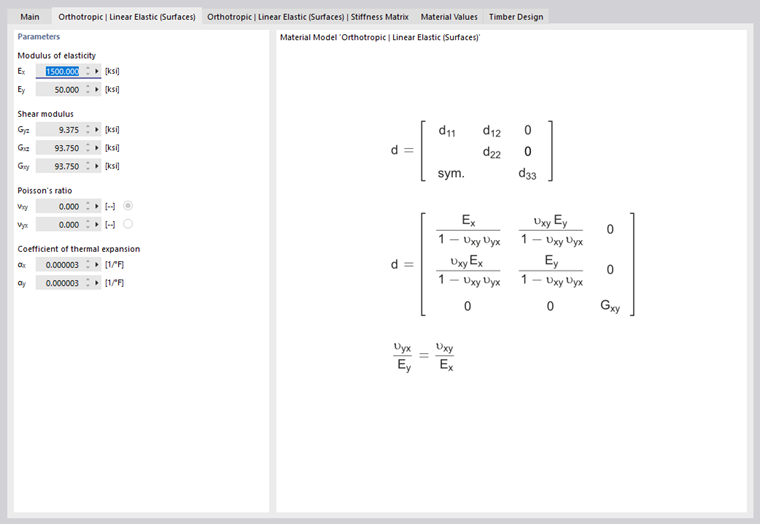
For a positive definite stiffness matrix, the following conditions must be fulfilled:
- Ex > 0; Ey > 0
- Gyz > 0; Gxz > 0; Gxy > 0
The Poisson's ratio can be defined for both orthotropy directions. The indices for νxy and νyx are assigned as follows: the first index stands for the strain in the stress direction, the second index for the negative strain perpendicular to the stress direction.
Orthotropic | Linear Elastic (Solids)
In the three-dimensional orthotropic material model, the elastic stiffnesses can be defined separately in all directions of the solid. To define different material properties for each direction, activate the User-Defined Material check box in the 'Options' section. In the Orthotropic | Linear Elastic (Solids) tab, you can then define the parameters of the material.
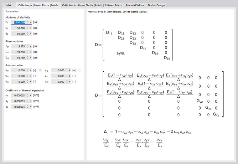
The stiffness matrix elements determined from the entries are specified in the 'Orthotropic | Linear Elastic (Solids) - Stiffness Matrix' tab.
Isotropic | Timber | Linear Elastic (Members)
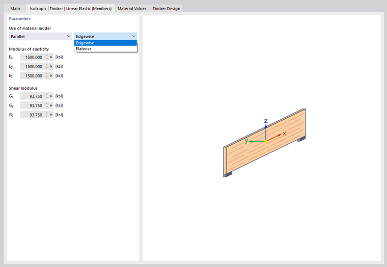
This material model is available for materials of the 'Timber' type. It allows you to model, for example, the properties of an OSB panel in a member model that takes into account the different stiffnesses depending on the installation position. You can define the position of the panel in the Isotropic | Timber | Linear Elastic (Members) tab using the two lists.
- banner.text
Orthotropic | Timber | Linear Elastic (Surfaces)
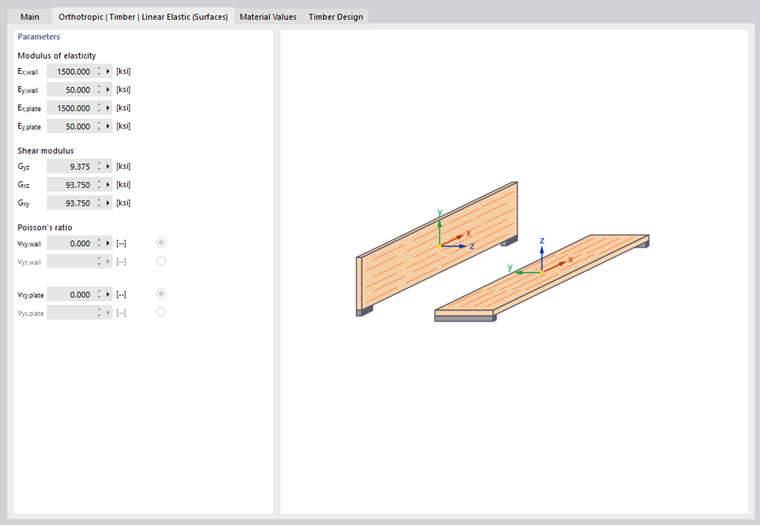
For materials of the 'Timber' type, this material model allows you to control the modulus of elasticity with regard to the structural behavior as a wall or slab, as well as the shear modulus Gxy: OSB panels, for example, have direction-dependent stiffnesses in the model depending on the installation position.
The stiffness parameters can be defined in the Orthotropic | Timber | Linear Elastic (Surfaces) tab. For timber materials from the library, standard values are preset. To define different material properties for each direction, first activate the User-Defined Material check box in the 'Options' section.
Basic Material Properties
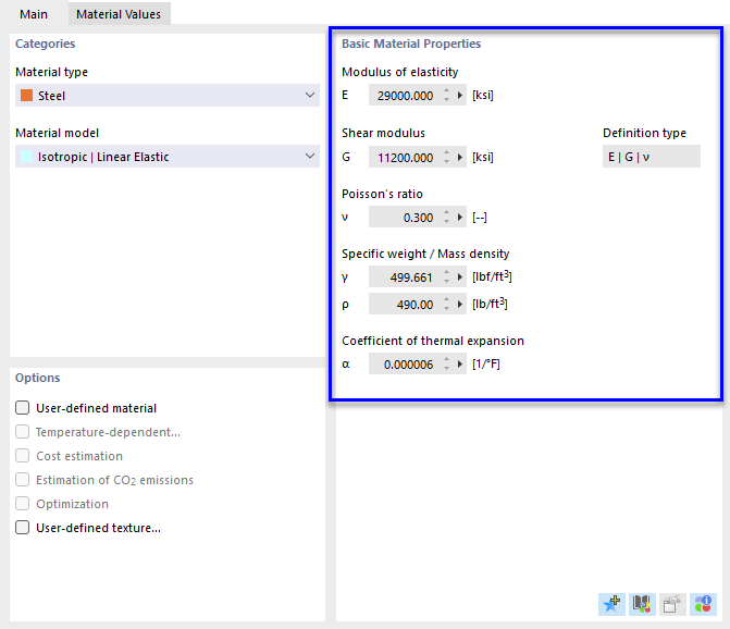
In this section of the 'Base' tab, the most important properties of the material are specified.
Modulus of Elasticity
The modulus of elasticity E describes the ratio between normal stress and strain.
Shear Modulus
The shear modulus G, also called modulus of rigidity, is the second characteristic value for describing the elastic behavior of a linear, isotropic, and homogeneous material. In this case, the deformation is based on a shear stress.
Poisson's Ratio
The Poisson's ratio ν, also called Poisson ratio, is required to determine the lateral strain. For isotropic materials, the Poisson's ratio usually lies between 0.0 and 0.5. From a value of 0.5 (e.g., rubber), it must therefore be assumed that the material is not isotropic.
The relationship between the modulus of elasticity, shear modulus, and Poisson's ratio for an isotropic material is described in equation Poisson's Ratio.
- banner.text
Options
The check boxes in this section of the 'Base' tab allow you to influence the material properties. After activating an option, new tabs are added.
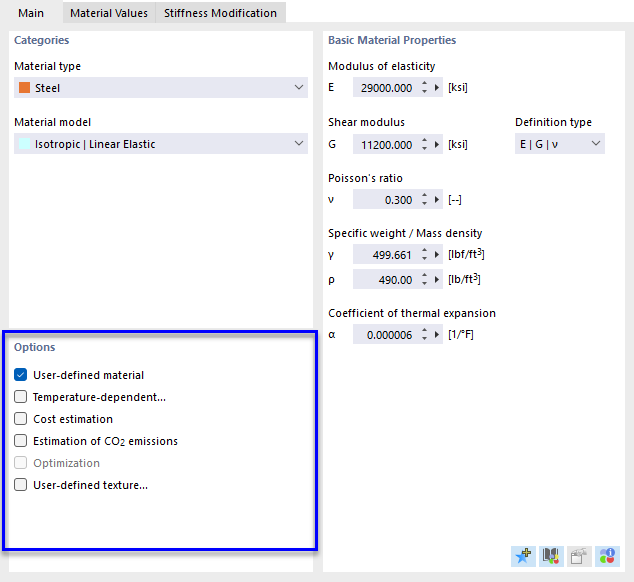
User-Defined Material
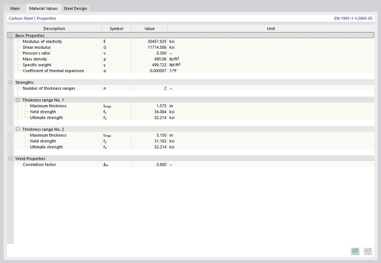
For materials from the library, the material properties are firmly preset. Therefore, they cannot be changed directly in the input fields. To adjust the properties of a material, activate the 'User-Defined Material' check box. This makes the input fields of the basic material properties in the 'Base' tab accessible. Likewise, you can change the design-specific properties in the 'Material Properties' tab (see image Adjusting Material Properties). In the 'Stiffness Modification' tab, it is possible to scale the E and G moduli globally with a factor (see image Adjusting Material Stiffness).
- banner.text
Temperature-Dependent
To define a linear elastic material with temperature-dependent stress-strain properties, activate the 'User-Defined' and 'Temperature-Dependent' check boxes. You can then define the temperature-dependent material properties in the Temperature-Dependent tab.
Cost Estimation
For determining the costs, the materials assigned to the individual objects are used. You can define the unit costs and units of the objects in the Cost Estimation tab.
Estimation of CO2 Emissions
The estimation of CO2 emissions is also based on the materials assigned to the individual objects. You can define the unit emissions and units in the Estimation of CO2 Emissions tab.
User-Defined Texture
With a user-defined texture, you can assign a surface structure to the material. The objects are then displayed very realistically in the rendering. In the 'User-Defined Texture' tab, select an existing entry or define a new texture using the button
 (see chapter Textures).
Material Properties
The Material Properties tab specifies all material properties that play a role in the structural analysis and the design in the add-ons.
- banner.info
Stiffness Modification
The Stiffness Modification tab is displayed if you have checked the User-Defined Material option in the 'Base' tab. Here you can adjust the stiffness of the material globally, for example to take into account safety factors or reduced material properties.
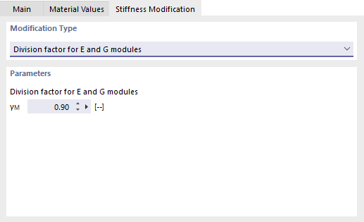
In the list of the 'Modification Type' section, two options are available for selection:
- Division factor for E and G moduli
- Multiplication factor for E and G moduli
In the 'Parameters' section, enter the factor by which the material stiffness is to be adjusted.
- banner.important
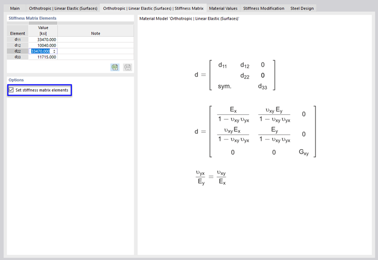
For a material with orthotropic properties, the E and G moduli as well as the Poisson's ratios can be adjusted in the Orthotropic | Linear Elastic tab (see image Stiffness Matrix). If you activate the 'Set stiffness matrix elements' option in the Orthotropic | Linear Elastic | Stiffness Matrix tab, you can also define the stiffness matrix elements manually.
Temperature-Dependent
The Temperature-Dependent tab is displayed if you have checked the User-Defined Material and Temperature-Dependent options in the 'Base' tab. Here you can describe the temperature-dependent properties of the material. The temperature-dependent material properties are taken into account for objects that are thermally loaded by temperature or temperature change. When calculating the temperature loads, the final temperature of the respective step is applied.
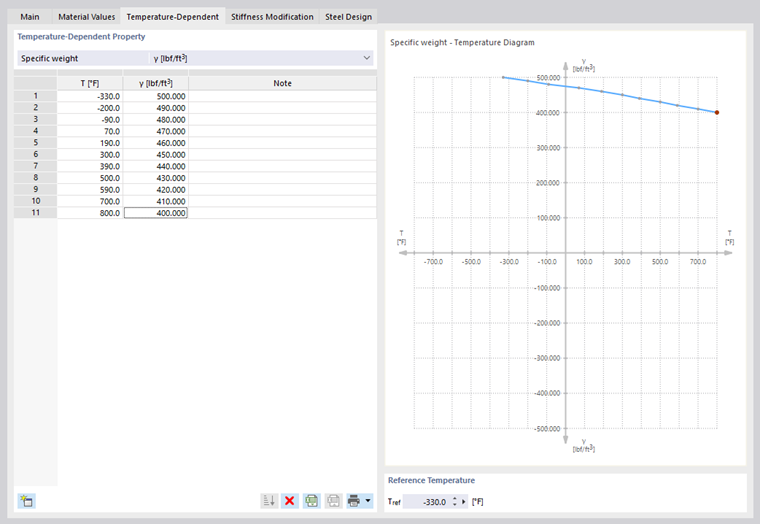
In the 'Temperature-Dependent Property' list, select a material property, for example the modulus of elasticity. Then use the button
to create the required table rows so that you can enter the temperatures with the associated values row by row. The data can also be imported from an Excel spreadsheet using the button
 .
.
The 'Reference Temperature' defines the stiffnesses for the objects that have no temperature loads. With a reference value of, for example, 300 °C, the reduced modulus of elasticity of this point of the temperature curve is applied for all members and surfaces.
User-Defined Material Library
You can save a user-defined material in a library as a template. This way, you do not need to define the material properties again in further projects.
- banner.tip
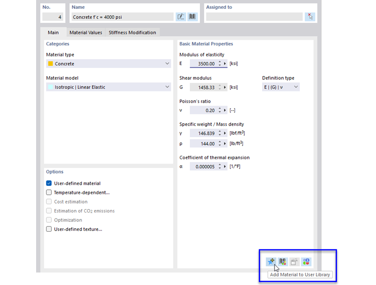
The 'New User-Defined Material' dialog box appears.
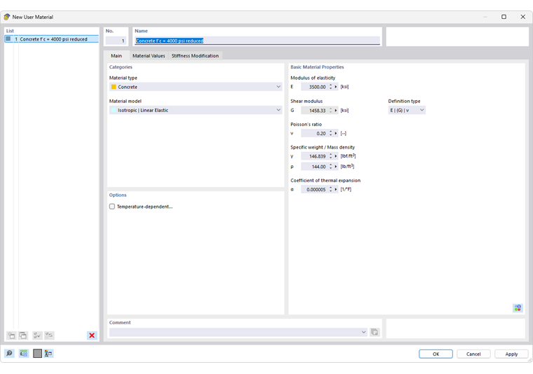
Enter the designation of the material in the 'Name' field. If necessary, you can also adjust the material properties. With OK, you then save the user-defined material in the library.
Importing Material
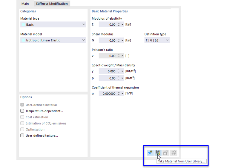
To import a user-defined material from the library, click the button
 in the 'Basic Material Properties' section.
The 'Edit User-Defined Material' dialog box appears. In this library with your saved materials (see image 'New User-Defined Material' Dialog Box), you can select the matching entry and then apply it with OK.
If you have imported a user-defined material and want to change the properties in general, you can adjust the material properties in the library using the button
 (in the 'Basic Material Properties' section).
Defining the Library Location
By default, the library with the user-defined materials is stored in the file user_library_material.dbm in the directory of the user configurations. You can check this directory in the Program Options.
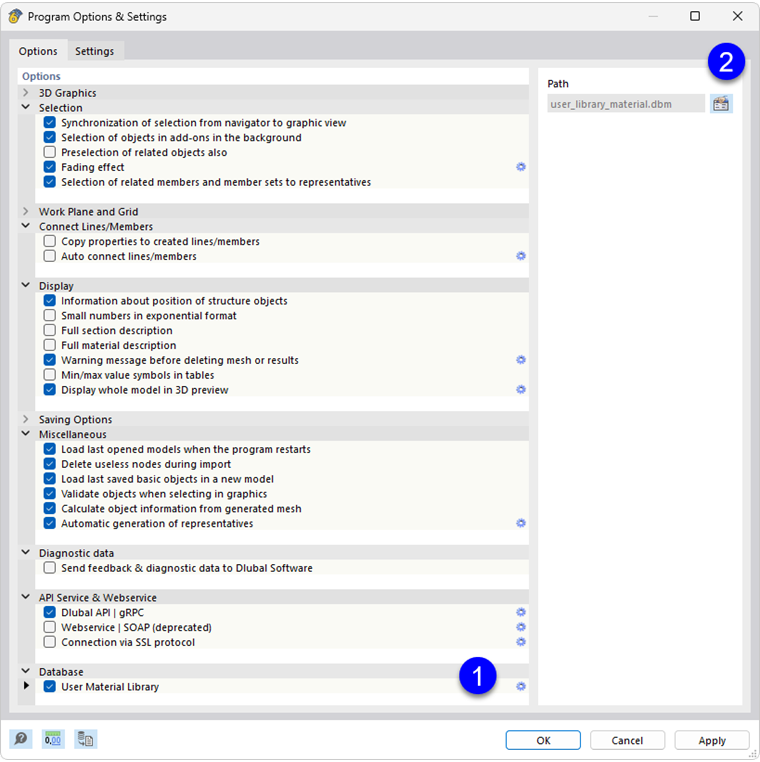
In the Library category, select the User material library entry (1). Then display the folder of the user_library_material.dbm file using the button
 (2). If you want to use a different material library located on a network drive of your company, define the directory of the file and click 'Save'. However, you can also transfer your file to another computer and set the storage path accordingly in the same dialog.
Cost Estimation
The Cost Estimation tab is displayed if you have checked the Cost Estimation option in the 'Base' tab.
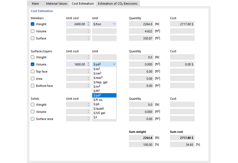
Check for the structural objects 'Members', 'Surfaces', and 'Solids' which characteristic value of the material is relevant for the cost estimation in each case: weight, volume, or surface, etc.
Enter in the 'Unit Costs' column the value that one unit of the material costs. Various options for the unit costs are available for selection in the list of the 'Unit' column.
- banner.text
Estimation of CO2 Emissions
The Estimation of CO2 Emissions tab is displayed if you have checked the Estimation of CO2 Emissions option in the 'Base' tab.
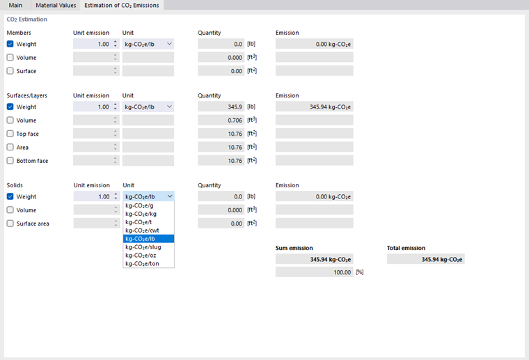
Check for the structural objects 'Members', 'Surfaces', and 'Solids' which characteristic value of the material is relevant for the estimation of CO2 emissions in each case: weight, volume, or surface, etc.
Enter in the 'Unit Emission' column the value of CO2 caused by one unit of the material. Various emission units for CO2 equivalents are available for selection in the list of the 'Unit' column.
From the unit emissions and the properties of the structural objects assigned to the material, the program determines the proportional CO2 emissions. The calculation is thus performed directly and not via a separate function as in other add-ons.
The 'Sum Emission' shows the CO2 equivalents resulting from summing up all activated partial emissions of the material. Furthermore, the proportion of the emissions that this material has of the total emissions of all materials activated for the estimation is displayed.
The 'Total Emission' results from adding up the sum emissions of all materials activated for the estimation of CO2 emissions.