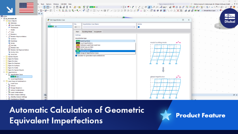
Imperfection cases describe the basic conditions of imperfections. Use them to define whether geometric imperfections or equivalent loads should be taken into account. Corresponding specifications can be found in the individual standards.
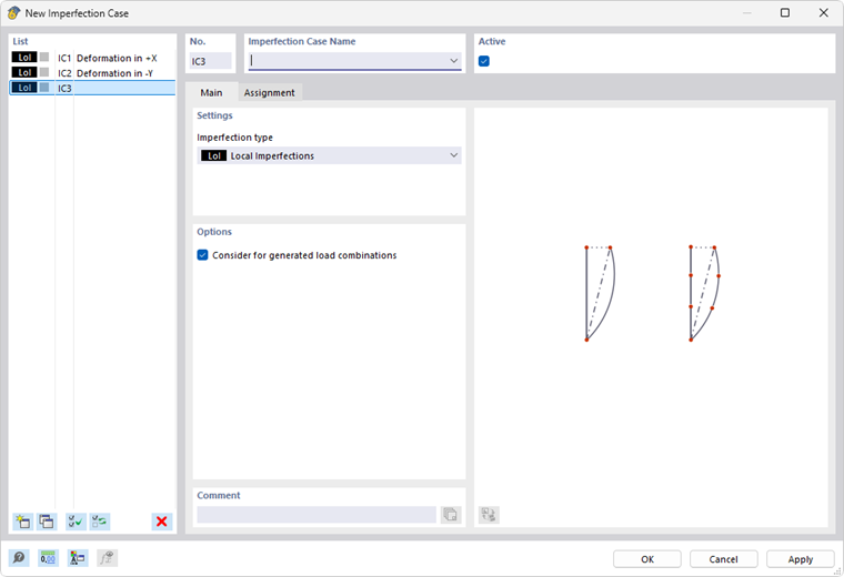
Main
The Main tab controls the type of imperfection. Imperfections can be taken into account, for example, in the form of equivalent loads, geometric pre-deformations, or inclinations by story.
In the Assignment tab, you can assign the imperfection case to specific load cases and combinations.
Settings
Various imperfection types are available for selection in the list.
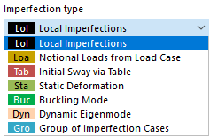
Local Imperfections
Imperfections are represented by equivalent loads. The inclinations and precambers depend on normal forces. You can define those imperfections in the Local Imperfections navigator category for members and member sets.
Notional Loads from Load Case
Imperfections are based on the loads of a particular load case. You can assign this load case in the Notional Loads from Load Case tab or create a new one.
Initial Sway via Table
This type of imperfection allows you to represent imperfections by story. Define the parameters in the Initial Sway via Table tab.
Static Deformation
Imperfections are based on the deformations of a load case or combination. Define the governing parameters in the Static Deformation tab.
In the "Source type" list, select whether the displacements are based on a load case or a load combination.
Buckling Mode
The imperfections are based on the mode shapes of a stability analysis. You can define the governing parameters in the Buckling Mode tab.
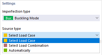
In the “Source Type” list, select whether the displacements are based on a load case or a load combination. However, the governing imperfection modes can also be determined automatically from the buckling modes for all assigned load cases and load combinations.
Dynamic Mode Shape
The imperfections are based on the mode shapes of a dynamic analysis. You can define the governing parameters in the Dynamic Mode Shape tab. The “Source Type” list only contains one option, since displacements in modal analyses can only be considered for load cases.
Group of Imperfection Cases
This imperfection type allows you to combine specifications from several imperfection cases. You can group the imperfection cases in the Group of Imperfection Cases tab and scale them by factors.
Options
The "Consider for generated load combinations" check box is activated by default. This option ensures that the imperfection case is taken into account for all load combinations that are not included by manual selection in the Assignment tab.
Example
In the "Assignment" tab, the "Wind" load case is assigned manually. Thus, all load combinations using this load case are assigned automatically. For load combinations without wind, however, the imperfection case is only considered if the "Assign to all load combinations without assigned imperfection case" option is activated.
Notional Loads from Load Case
Notional loads are available as an imperfection type (see the image Selecting Imperfection Type).
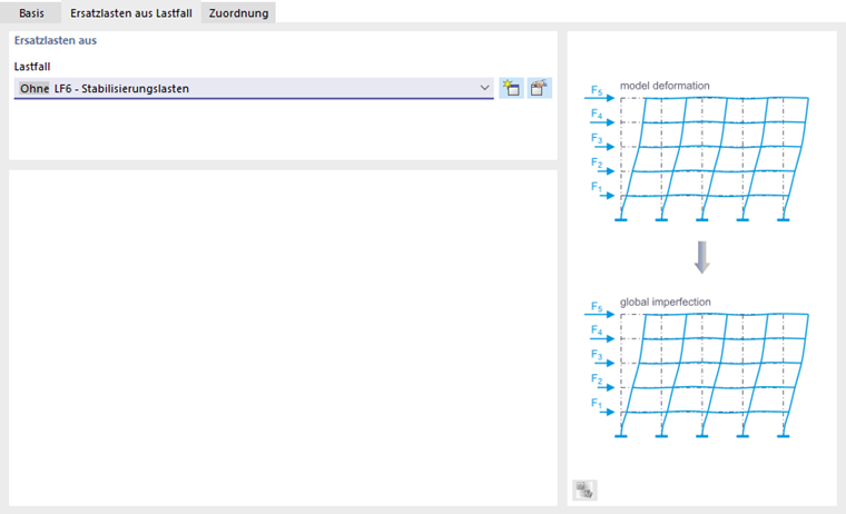
You can describe those imperfections in a load case by equivalent loads. Assign the load case category None to this load case so that it is not taken into account in the combinatorics, but only as an imperfection load case. This allows you to define stabilizing loads independently of axial forces, for example, in contrast to inclinations or "notional loads", which act as equivalent loads related to axial forces.
Select the load case in the list, or create a new load case with the
 button.
Initial Sway via Table
The Initial Sway is available as an imperfection type (see the image Selecting Imperfection Type).
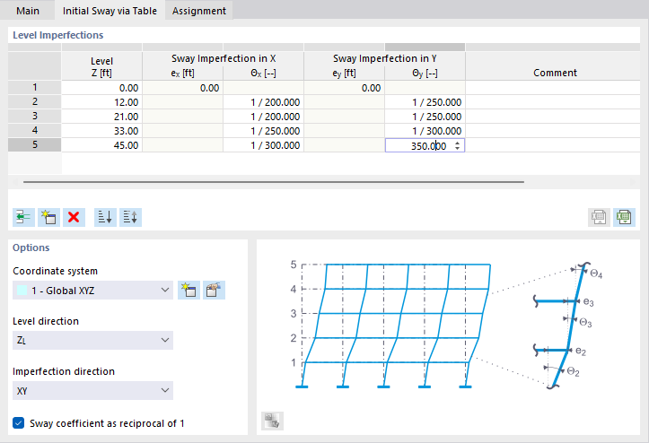
Level Imperfections
You can describe the normative displacement of a building in a table. Thus, you do not need to define imperfections for each individual column. The floor levels of the table control how nodes are moved within the building sections.
Define the ordinates of the stories and assign the inclinations. Use the
button to add rows. Make sure that the ordinates are set in ascending order. Based on these specifications, RFEM determines a geometric displacement and applies it to the FE nodes.
Options
If the imperfections are not to be related to the global XYZ coordinate system, you can select a user-defined "Coordinate system" or create a new one. The "Level direction" specifies the ordinate of the stories; thus, vertically oriented initial sways are also possible.
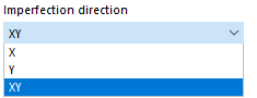
The "Imperfection direction" defines the direction(s) in which inclinations are applied. With "XY" as the default setting, inclinations in the table are specified for the directions X and Y. If they act in only one direction, define the corresponding axis in the list.
In the table, the "Sway coefficient" is displayed "as a reciprocal of 1". If you deactivate the check box, the values appear as decimal numbers.
Static Deformation
The Static Deformation is available as an imperfection type (see the image Selecting Imperfection Type).
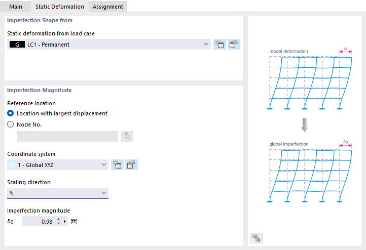
The "Imperfection Shape" is based on the deformations of a load case or combination. The geometric pre-deformations are scaled to a magnitude.
Imperfection Shape from
Select the governing load case or combination in the list. Use the
button to create a new load case or combination.
Imperfection Magnitude
The "Reference location" defines the location in the model whose displacement serves as a reference for the sagitta. Usually, this is the location with the greatest displacement. However, you can also select another node in the list or define it graphically with the
 button.
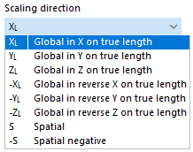
If the imperfections are not to be related to the global XYZ coordinate system, you can select a user-defined "Coordinate system" or create a new one. The "Scaling direction" defines the orientation of imperfections. The "S" and "-S"options allow for imperfections that are spatial, such as those occurring in shell models.
Enter the "Imperfection magnitude" that represents the maximum geometric displacement. The displacements of the FE nodes are scaled to this value. The deformation of the load case or combination specified above forms the basis.
Buckling Mode
The parameters of the Buckling Mode imperfection type can be defined when the critical load is calculated for a load case or load combination using the Structure Stability add-on. The concept of the tab is aligned with the load type.
Buckling Mode from Load Case/Load Combination
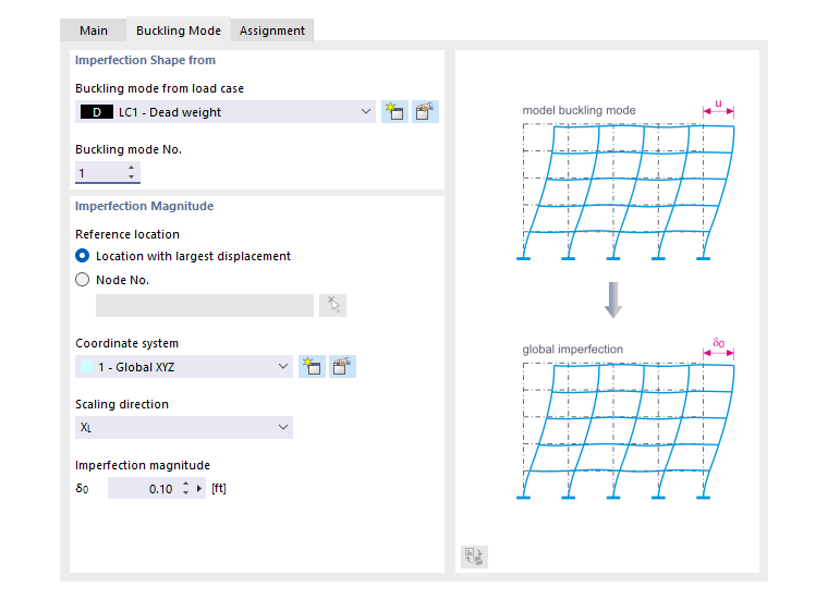
The “Imperfection mode” is based on the eigenvalues of a load case or load combination. The mode shapes are scaled to a fixed dimension.
Imperfection Mode from
Select the governing load case or governing load combination from the list. Use the
button to create a new load case or load combination. Then specify the buckling mode on which the imperfections are to be based in the list.
Imperfection Magnitude
The Reference Point specifies the location in the model whose displacement serves as a reference for the magnitude. This is usually the point with the largest displacement. However, you can also select another node from the list or define it graphically using the
button.
If the imperfections are not to be related to the global XYZ coordinate system, you can select or create a user-defined coordinate system. The Scaling direction determines the orientation of the imperfections. The “S” and “-S” options allow for spatial imperfections, such as those occurring in shell models (see the image Select Scaling Direction).
Enter the Imperfection magnitude that represents the maximum geometric displacement. The displacements of the FE nodes are scaled to this value. The deformation of the load case or combination specified above forms the basis.
Automatic Imperfections
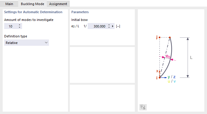
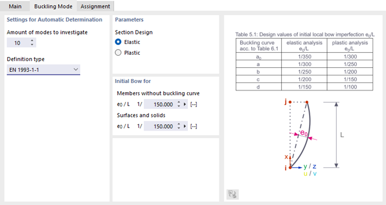
In the automatic determination of imperfections, the imperfection mode is derived from the current load-dependent mode shape of the model and scaled by the defined imperfection amplitude.
Settings for Automatic Determination
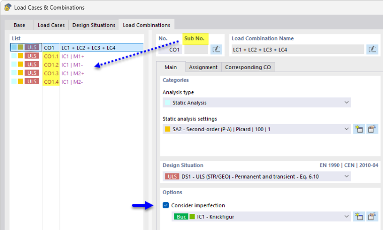
Specify the amount of modes to be investigated. Please note the following: For each load case and each load combination, so-called “sub-load cases” or “sub-load combinations” are generated, in which the imperfection mode is taken into account. This results in two sub-load cases or sub-combinations per mode shape, since each mode shape is scaled once in the positive direction and once in the negative direction. These sub-load cases and sub-combinations can then be analyzed just like normal load cases or load combinations.
Example: You have assigned automatic imperfections to Load Case 1 (LC1) and specified two shapes to be analyzed. This generates the subload combinations CO1.1 through CO1.4—that is, four sub-load combinations.
The Definition type allows for control of the input for scaling mode shapes. The list currently offers two options for selection:
- Relative: You can specify the maximum imperfection magnitude directly in the “Parameters” section (see the mage Set Parameters for Automatic Determination of Imperfections). This imperfection magnitude depends on the virtual effective length of the object with the maximum amplitude within the mode shape.
- EN 1993-1-1: The imperfection magnitude is determined according to the standard-compliant requirements specified in EN 1993-1-1, Table 5.1. In the following sections, you can adjust the imperfection parameters.
Parameters
Specify whether the cross-section analysis should be performed using the “Elastic” or “Plastic” method. The imperfection magnitudes to be used depend on this selection.
Initial Bow for
The buckling curve of the cross-sections is generally known. For “Members without buckling curve” (with an unknown buckling curve), you can specify the value manually. The same applies to “Surfaces and solids” that do not have a buckling curve according to EN 1993-1-1.
Dynamic Eigenmode
The parameters of the Dynamic Eigenmode imperfection type can be defined when performing a modal analysis for a load case or load combination.
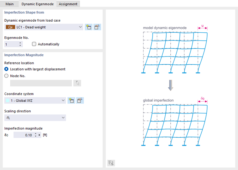
The “Imperfection shape” is based on the dynamic eigenvalues of a load case or load combination. The mode shapes are scaled to a reference dimension.
Imperfection Shape from
Select the governing load case or load combination from the list. Use the
button to create a new load case or load combination. Then, specify the mode shape on which the imperfections are to be based in the list. With the ‘“Automatically”’ option, the program determines the governing mode shape.
Imperfection Magnitude
You can define the parameters as described in the section Imperfection magnitude for a buckling mode.
Group of Imperfection Cases
The Group of Imperfection Cases is available as an imperfection type (see the image Selecting Imperfection Type).
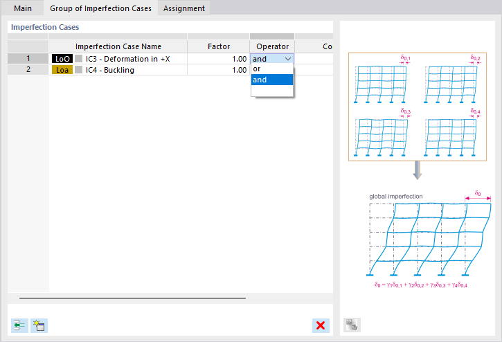
You can combine several imperfection cases in one group and thus consider them at the same time. This option is often useful for shell buckling in order to apply global imperfections and local buckling.
Define the imperfection cases to be combined. Use the
button to add rows to the table.
You can apply a "Factor" to each imperfection case. Use the "Operator" to define whether the imperfection cases act simultaneously ("and") or are mutually exclusive ("or").
Assignment
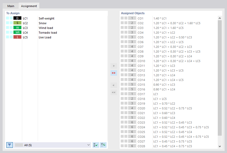
In the Assignment tab, you can assign one or more load cases or load combinations to the imperfection case. Only then is the imperfection case considered in the calculation.
Assign
The "To Assign" column lists all the load cases you have created. To transfer a load case to the "Assigned Objects" list, you can use the following possibilities:
- Double-click the load case.
- Select the load case. Then, click the
 button.
Assigned Objects
The "Assigned Objects" column manages all load cases that you assign to the imperfection case. For example, if you want to consider the imperfection case "Wind in +X" by the load case "Wind in +X", transfer this load case to the list as described above. If the Combination Wizard is active, all load combinations using this load case are assigned, too.
This way, you can compare imperfection cases with the acting directions of load cases: For example, an imperfection case with inclinations in X acts for wind loading in X; an imperfection case in Y, for wind loading in Y. For unassigned load combinations (those without wind loads), each imperfection case is considered separately. RFEM creates two load combinations each with identical superposition criteria, but different imperfection cases.