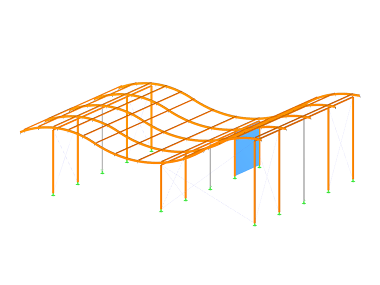
The geometry of model objects is defined by lines. They are essential for creating surfaces, members, and solids. When entering members or surfaces graphically, lines are created automatically.
Every line is defined by a start and an end node. To define complex types of lines, intermediate nodes are required.
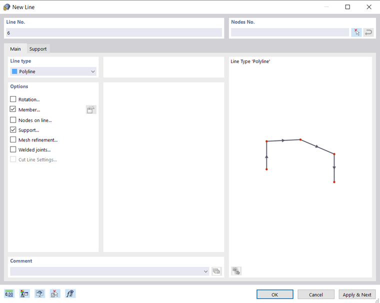
The line number is assigned automatically, but it can be changed. The order is irrelevant for the numbering. It does not have to be continuous, either; gaps in the numbering are allowed.
Main
The Main tab manages the most important line parameters.
Line Type
Various line types are available for selection in the list.
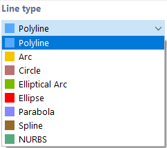
Single Line / Polyline
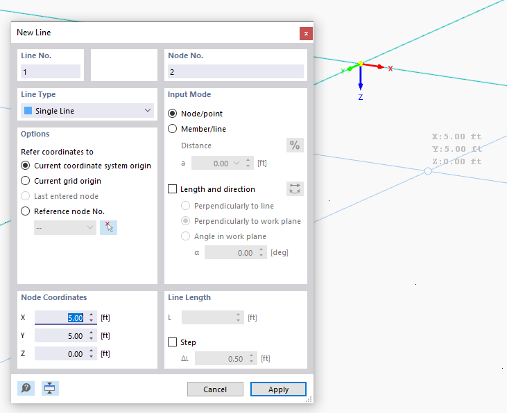
The "New Line" dialog box, which appears when the pull-down menu is used, is shown in the image New Line. The image above shows the input dialog for box graphical input, which is started using the
 button.
A Single Line is defined by a start node and an end node. It represents a direct connection between both nodes.
A Polyline is a polygonal chain consisting of several straight line segments. Therefore, the dialog box (see the image New Line) shows the numbers of the intermediate nodes in addition to those of the start and end nodes. For the sake of simplicity, single lines are managed as polylines, too.
When entering polylines graphically, existing nodes, grid points, or snap objects can be selected as definition nodes. However, you can also set nodes freely into the work plane.
Arc
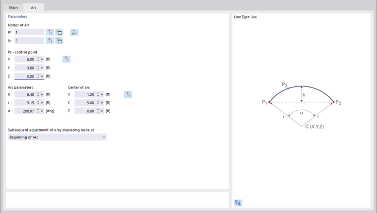
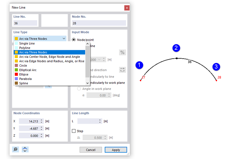
An arc is defined by three nodes. In the "Arc" tab, you can enter the start node P1, the end node P2, and the control point P3; you can also select them graphically or create new ones. The graphic illustrates the node order.
Based on these three nodes, RFEM determines the "Arc parameters": the rise h, the radius r, the opening angle α, and the arc center. If you change a parameter, the node coordinates will be adjusted accordingly. When changing the opening angle, you can use the list to define which of the three definition nodes should be moved.
If you define the arc graphically using the
button, you can select the nodes directly in the work window or set new ones.
Circle
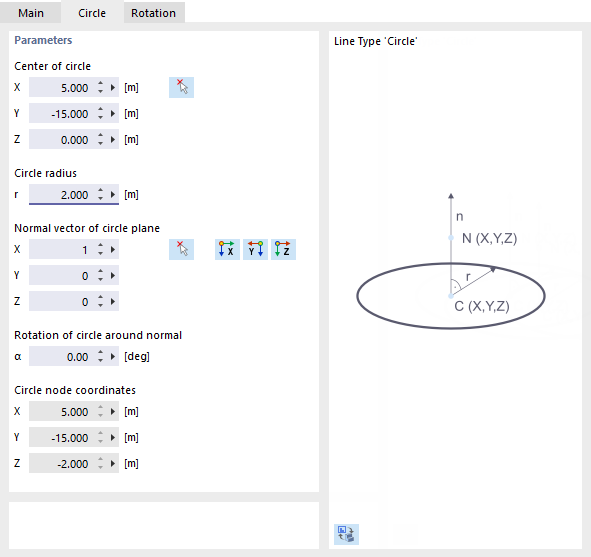
A circle is defined by its center and the radius. In the "Circle" tab, you can enter or graphically define the coordinates of the circle center and specify the circle radius. The normal vector controls the plane in which the circle is generated. You can use the buttons to select this vector to specify an inclined plane or define one of the global axes. The rotation of the circle about the normal defines the control point on the circle line. Its coordinates are specified in the last three fields.
When defining the circle graphically using the
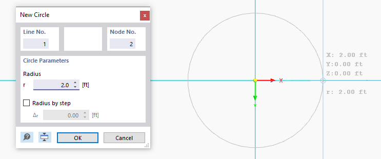
 button, you can define the center and radius in the work window by clicking the corresponding points.
Elliptical Arc
This line type can be used to create a conic section. Define three control points for the ellipse and the arc angle in the "Elliptical Arc" tab (see the image Arc Parameters).
Ellipse
To define an ellipse, three nodes are required. To define the principal axis of the ellipse, you can enter the two nodes P1 and P2, select them graphically, or define new nodes in the "Ellipse" tab. The control point P3 describes the length of the minor axis.
Parabola
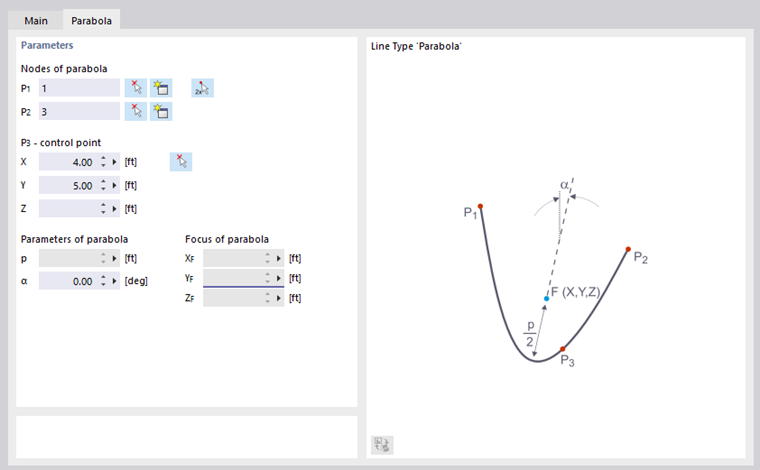
This line type can be used to create a conic section. Define the two end nodes of the parabola and the control point in the "Parabola" tab. Based on this information, RFEM determines the parameters of the parabola as well as the focus.
Spline
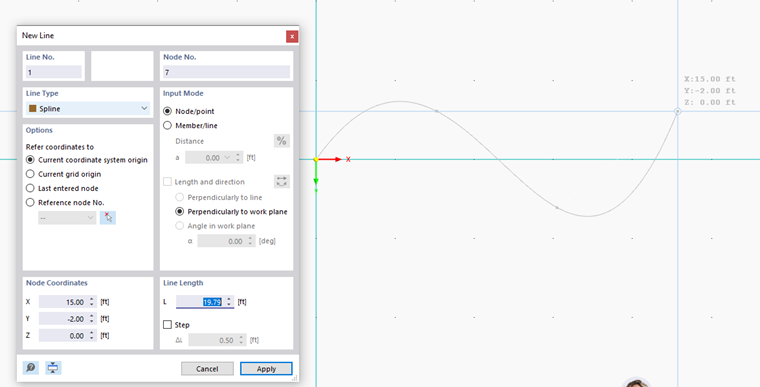
Splines can be used to model any kind of curve. To do so, use the
 button in the "Node No." section to select the nodes of the curved line one after the other.
If you define the spline graphically using the
 button, you can specify or redefine the nodes in the work window with a click.
NURBS
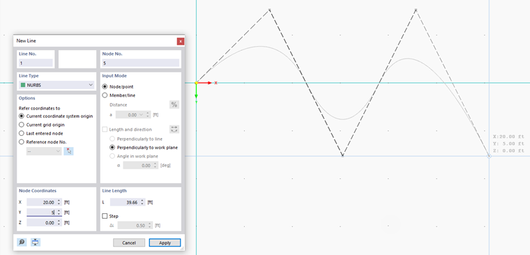
NURBS (non-uniform rational basis splines) are required for modeling freeform surfaces. NURBS are splines whose control points do not lie on the curve itself. You can define NURBS graphically by defining the control points one by one with a mouse click.
Rotation
The Rotation tab offers various options for rotating the line. If the "Angle" option is set, specify the angle β by which the local line axis x should be rotated. A positive value causes a clockwise rotation along the positive x-axis.
The line axis system can also be aligned to a "Help node". You can select this node graphically or create a new one. Then, enter the reference plane x-y or x-z.
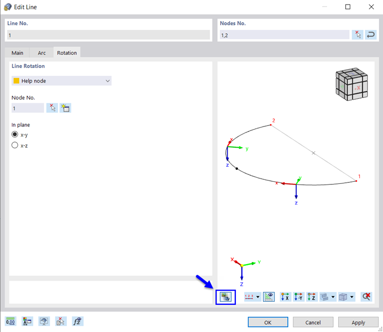
You can use the
 button to check the line axes in the model view.
The "Inside" option is useful for aligning curved or segmented lines to the center.
Rotating a line can facilitate the input of line loads acting in the local line direction y or z. The line rotation does not affect surfaces or members, because they have their own coordinate system.
Member
Member properties can be assigned to any line (see the chapter Members).
Nodes on Line
This node type can be used to set nodes on the line without dividing the line (see the image Defining Node on Line ).
Support
A line support can be assigned to any line (see the chapter Line Supports).
Mesh Refinement
The line can be appropriately discretized by mesh refinements (see the chapter Line Mesh Refinements).
Welded Joints
If several surfaces are rigidly connected to the line using welds, the connection type can be described in detail (see the chapter Line Welded Joints).
Cut Line Settings
The check box is accessible when membrane surfaces are created for the "Cutting Pattern" add-on (in preparation). This way, specifications for cutting lines of membrane cuts can be made.