Material models
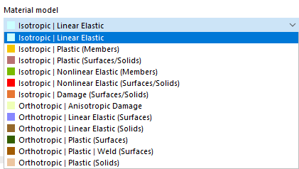
If the analysis add-on Nonlinear material behavior is activated in the Model base data (license required), further options are available for selection in the list of material models in addition to the Isotropic | Linear elastic and Orthotropic | Linear elastic material models.
Calculation method
When using a nonlinear material model, an iterative calculation is always performed. Depending on the material model, a different relation between stresses and strains is defined.
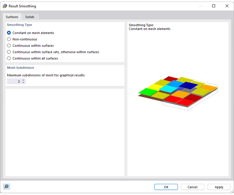
The stiffness of the finite elements is adjusted repeatedly during the iterations until the stress-strain relation is fulfilled. The adjustment is always applied to an entire surface or solid element. Therefore, the smoothing type Constant in mesh elements should always be used for the stress analysis.
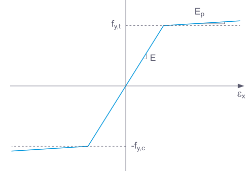
Some material models in RFEM are labeled 'plastic', others 'nonlinear elastic'. If a component with a nonlinear elastic material is unloaded again, the strain returns along the same path. After complete load relief, no strain remains.
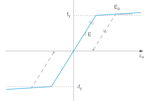
When unloading a component with a plastic material model, a strain remains after complete unloading.
Loading and unloading can be simulated with the add-on Construction stages analysis.
Background information on the nonlinear material models can be found in the technical article Yield laws in the isotropic nonlinear elastic material model.
The internal forces in slabs with nonlinear materials result from the numerical integration of the stresses over the plate thickness. To define the integration method for the thickness, check the option Specify integration method in the 'Edit Thickness' dialog. This provides the following integration methods for selection:
- Gauss-Lobatto quadrature
- Simpson's rule
- trapezoidal rule
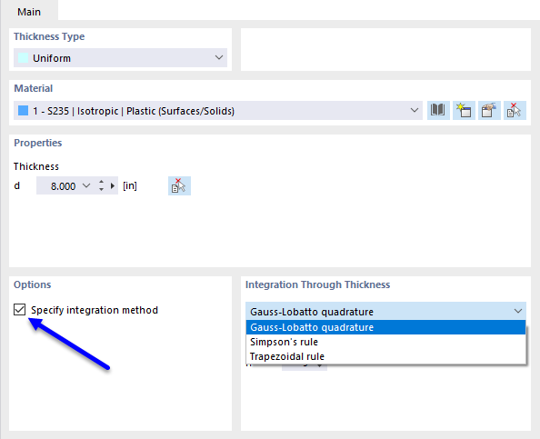
Furthermore, you can define the 'number of integration points' over the plate thickness from 3 to 99.
Isotropic plastic (members)
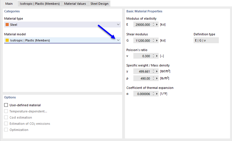
If you select the entry Isotropic | Plastic (members) in the 'Material model' drop-down list, the tab for entering the nonlinear material parameters becomes active.
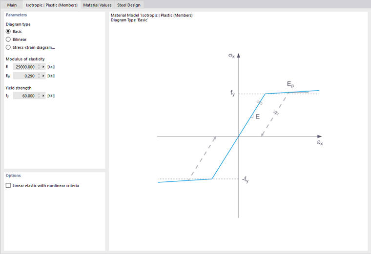
In this tab, you define the stress-strain diagram. The following options are available for selection:
- Standard
- Bilinear
- Diagram
If Standard is selected, RFEM uses a bilinear material model. For the modulus of elasticity E and the yield strength fy, the values from the material library are used. For numerical reasons, the branch is not exactly horizontal but has a small slope Ep.
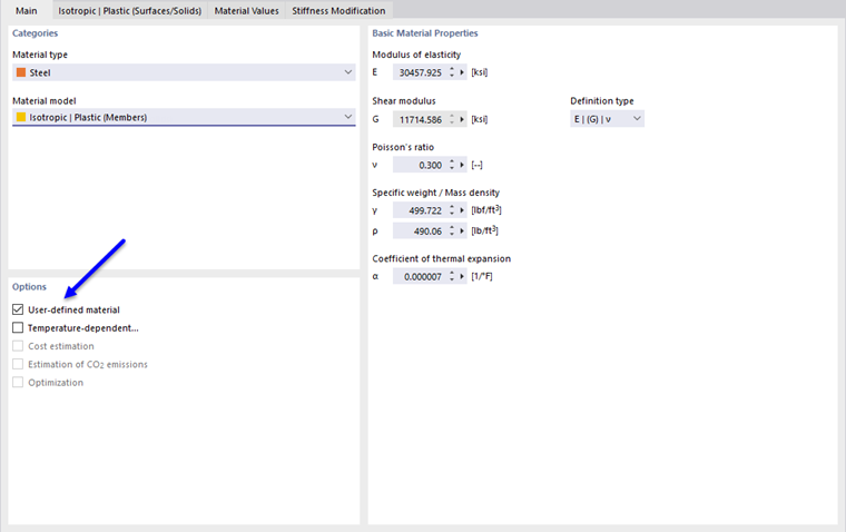
If you want to change the values for the yield strength and the modulus of elasticity, activate the User-defined material check box in the 'Basic' tab.
With the bilinear definition, you can also enter the value for Ep.
You can define more complex relations between stress and strain using a stress-strain diagram. If you select this option, the 'Stress-Strain Diagram' tab is displayed.
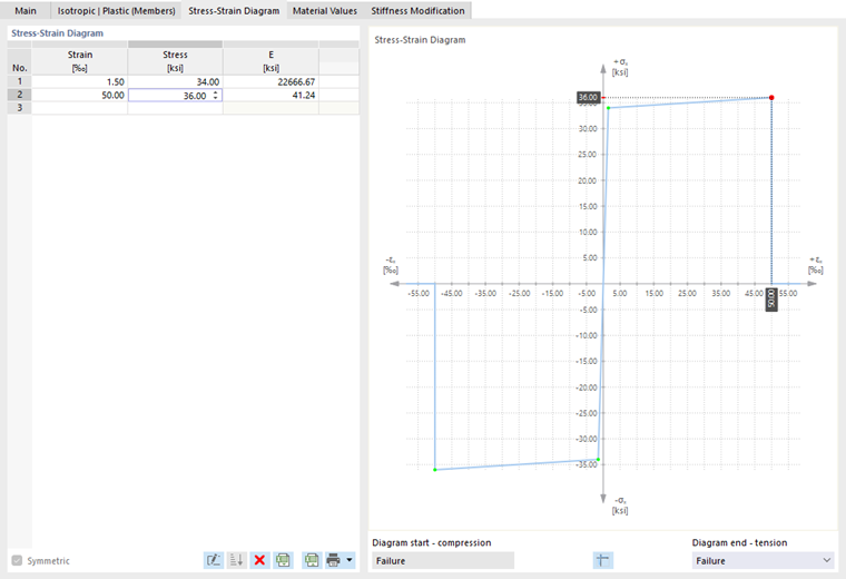
Define a point of the stress-strain relation in each row. How the diagram should continue after the last definition point can be selected in the 'Diagram end' list below the diagram:
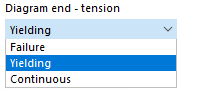
With 'Failure', the stress jumps back to zero after the last definition point (for example, when the material tears). 'Yielding' means that the stress remains constant with increasing strain. 'Continuous' means that the curve continues with the slope of the last segment.
Isotropic plastic (surfaces/solids)
If you select the entry Isotropic | Plastic (surfaces/solids) in the 'Material model' drop-down list, the tab for entering the nonlinear material parameters becomes active.
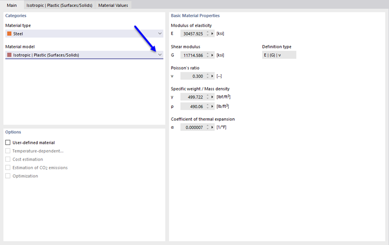
First, select the 'stress failure hypothesis'. The following hypotheses are available for selection:
- von Mises (distortion energy hypothesis)
- Tresca (shear stress hypothesis)
- Drucker-Prager
- Mohr-Coulomb
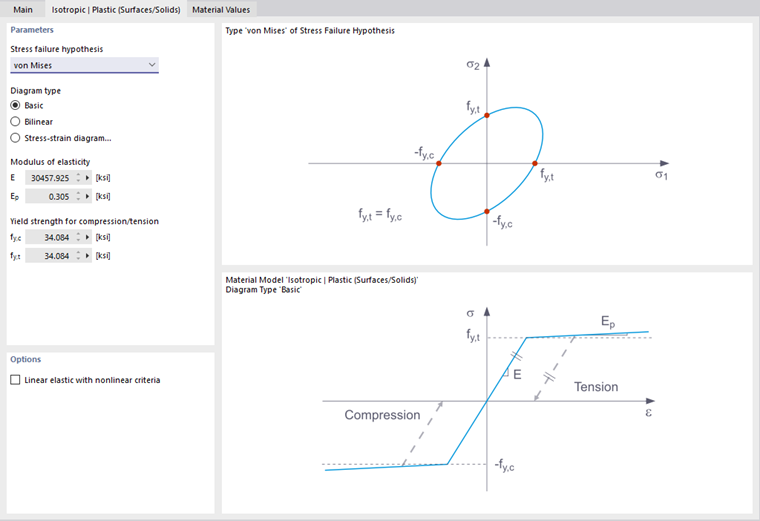
If you select von Mises, the following stresses are used in the stress-strain diagram:
- Surfaces
- Solids
According to the Tresca hypothesis, these stresses are used:
- Surfaces
- Solids
According to the Drucker-Prager hypothesis, this stress is used for surfaces and solids:
|
σc |
Limit stress for compression |
|
σt |
Limit stress for tension |
According to the Mohr-Coulomb hypothesis, the following stress is used for surfaces and solids:
Isotropic nonlinear elastic (members)
The functionality largely corresponds to that of the Isotropic plastic (members) material model. However, unlike this model, no plastic strain remains after unloading.
Isotropic nonlinear elastic (surfaces/solids)
The functionality largely corresponds to that of the Isotropic plastic (surfaces/solids) material model. However, unlike this model, no plastic strain remains after unloading.
Isotropic damage (surfaces/solids)
Unlike other material models, the stress-strain diagram for this material model is not antimetric to the origin. Thus, for example, the behavior of steel fiber reinforced concrete can be modeled with this material model. Detailed information on modeling steel fiber reinforced concrete can be found in the technical article Material properties of steel fiber reinforced concrete.
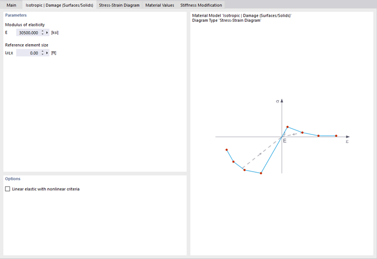
The isotropic stiffness is reduced by a scalar damage parameter. This damage parameter is determined from the stress curve defined in the diagram. The direction of the principal stresses is not taken into account; rather, the damage occurs in the direction of the equivalent strain, which also covers the third direction perpendicular to the plane. The tension and compression zones of the stress tensor are treated separately. Different damage parameters apply in each case.
The 'reference element size' controls how the strain in the crack area is scaled to the length of the element. With the default value of zero, no scaling takes place. This realistically represents the material behavior of steel fiber reinforced concrete.
Orthotropic plastic (surfaces) / Orthotropic plastic (solids)
The material model according to Tsai-Wu combines plastic and orthotropic properties. This allows special modeling of materials with anisotropic characteristics such as fiber-reinforced plastics or timber.
When the material yields, the stresses remain constant. A redistribution takes place depending on the stiffnesses present in the individual directions.
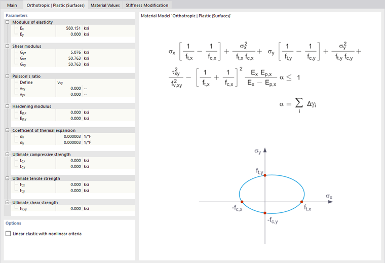
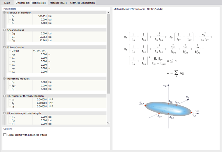
The elastic range corresponds to the Orthotropic linear elastic (solids) material model. The following yield condition according to Tsai-Wu applies for the plastic range:
- Surfaces
- Solids
All strengths must be defined as positive.
The yield condition can be imagined as an elliptical surface in the six-dimensional stress space. If one of the three stress components is set as a constant value, the surface can be projected onto a three-dimensional stress space.
If the value for fy(σ) according to equation Tsai-Wu, state of plane stress is less than 1, the stresses are in the elastic range. The plastic range is reached as soon as fy(σ) = 1. Values greater than 1 are not allowed. The model behaves in an ideally plastic manner, that is, no stiffening takes place.
Orthotropic plastic weld (surfaces)
This material model is used for analyses with the add-on Steel joints in order to represent the behavior of welds in accordance with the standards. In the equivalent surface, only stresses occur that correspond to the stress components σ⊥, τ⊥, and τ|| of the weld. In the other stress directions, the stiffness of the equivalent surface approaches zero.

In the 'Orthotropic | Plastic | Weld (Surfaces)' tab, you can define the parameters for taking into account the plastic material hardening of welds, for example the limit values fekv and fx for the stress analysis according to the "directional method" according to EN 1993-1-8 [1] for welds, modified by a plastic component (see also the technical article Design of fillet welds).
Concrete
For the 'Concrete' material type, the nonlinear material models Anisotropic | Damage and Isotropic | Damage (surfaces/solids) are available for selection.
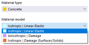
These material models are described in the chapter Anisotropic | Damage of the Concrete manual or above in the section Isotropic Damage.
Masonry
If the design add-on Masonry Design is activated in the Model base data (license required), the nonlinear material models Isotropic | Masonry | Plastic (surfaces) and Orthotropic | Masonry | Plastic (surfaces) are available for the 'Masonry' material type.
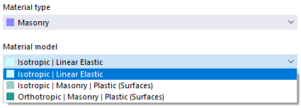
Both material models are described in the chapter Materials of the Masonry manual.
Fabric
For the 'Fabric' material type, the nonlinear material model Orthotropic | Fabric | Nonlinear elastic (surfaces) is available in addition to the orthotropic linear material model.
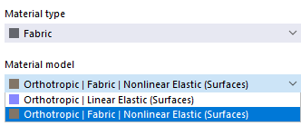
This material model allows for a realistic representation of the orthotropic behavior of prestressed fabric membranes in which the stiffnesses in warp and weft are different. It describes the fabric using a representative volume element (RVE) of its microstructure. By taking the fabric geometry into account, the model captures the associated transverse strain effect for all force states in the membrane. The load-dependent stiffness development of the fabric is also taken into account, which is essential for the accurate analysis of membrane structures.
The description is in progress.