Material Models
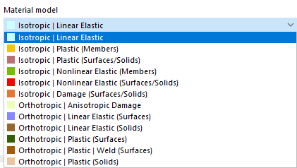
If the Nonlinear Material Behavior analysis add-on (requires a license) is activated in the Model Base Data, further options are available in the list of material models in addition to the Isotropic | Linear Elastic and | Linear Elastic material models.
Calculation Method
If you use a nonlinear material model, an iterative calculation is always performed. Depending on the material model, a different relation between the stresses and strains is defined.
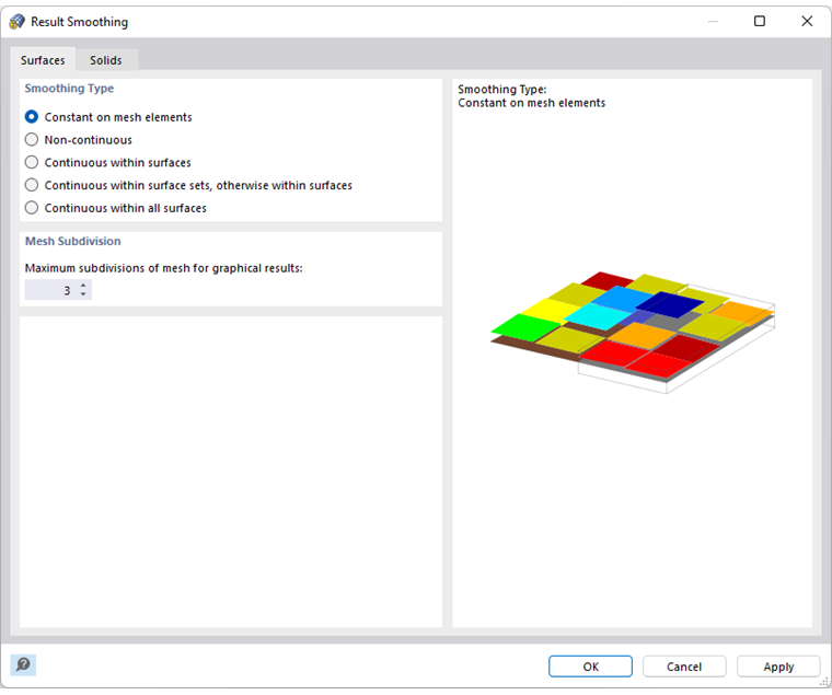
The stiffness of the finite elements is repeatedly adjusted in the course of the iterations until the stress-strain relation is complied with. The adjustment is always carried out for an entire surface or solid element. The Constant on mesh elements smoothing type should, therefore, always be used when evaluating stresses.
Plastic and Non-Elastic Material Models
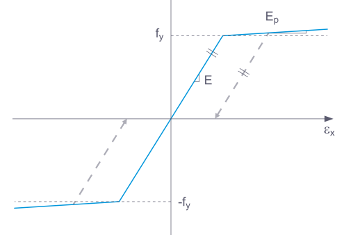
Some material models in RFEM are labeled as "Plastic", others as "Nonlinear Elastic". If a structural component with a nonlinear elastic material is relieved of loads again, the strain decreases along the same path. When the load is completely removed, no strain remains.
When a component is relieved of loads with a plastic material model, a strain remains after complete unloading.
Loading and unloading can be simulated using the Construction Stages Analysis add-on.
Surface Internal Forces
The internal forces in plates with nonlinear material result from the numerical integration of the stresses over the plate thickness. To define the integration method for the thickness, select the Specify integration method option in the "Edit Thickness" dialog box. The following integration methods are available:
- Gauss-Lobatto quadrature
- Simpson's rule
- Trapezoidal rule
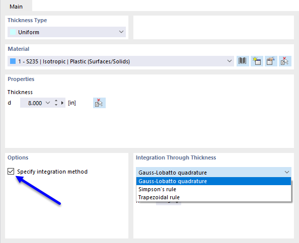
You can also specify the "Number of integration points" from 3 to 99 via the plate thickness.
Isotropic | Plastic (Members)
If you select Isotropic | Plastic (Members) from the "Material model" drop-down list, the tab for entering the nonlinear material parameters is activated.
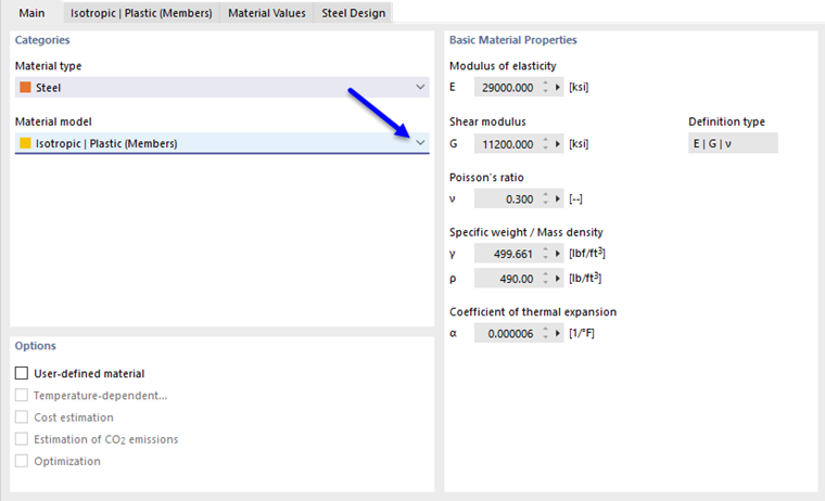
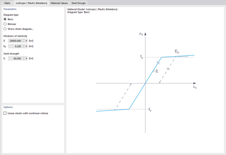
In this tab, you define the stress-strain diagram. The following options are available:
- Basic
- Bilinear
- Diagram
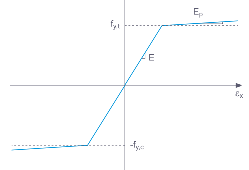
If you select Basic, RFEM uses a bilinear material model. The values from the material library are used for the modulus of elasticity E and the yield strength fy. For numerical reasons, the diagram branch is not exactly horizontal, but has a small slope Ep.
If you want to change the values for the yield strength and the modulus of elasticity, activate the User-defined material check box in the "Main" tab.
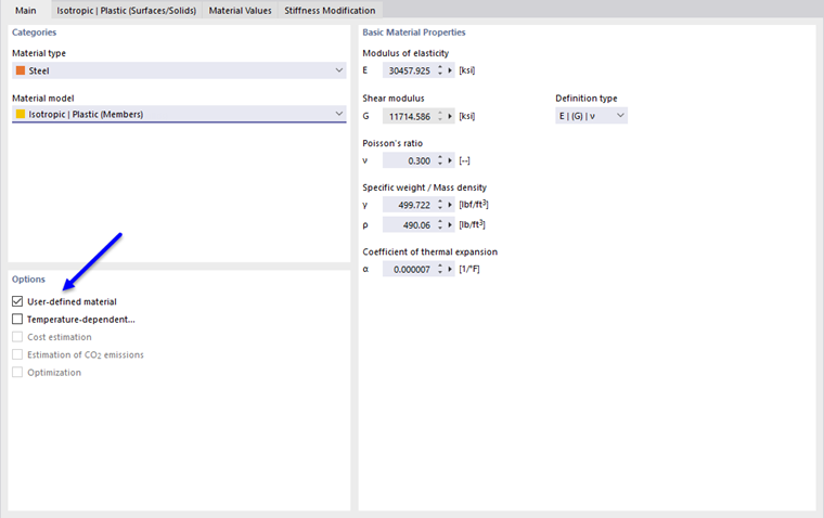
For a bilinear definition, you can also enter a value for Ep.
More complex relations between stress and strain can be defined by means of the Stress-strain diagram. If you select this option, the "Stress-Strain Diagram" tab is displayed.
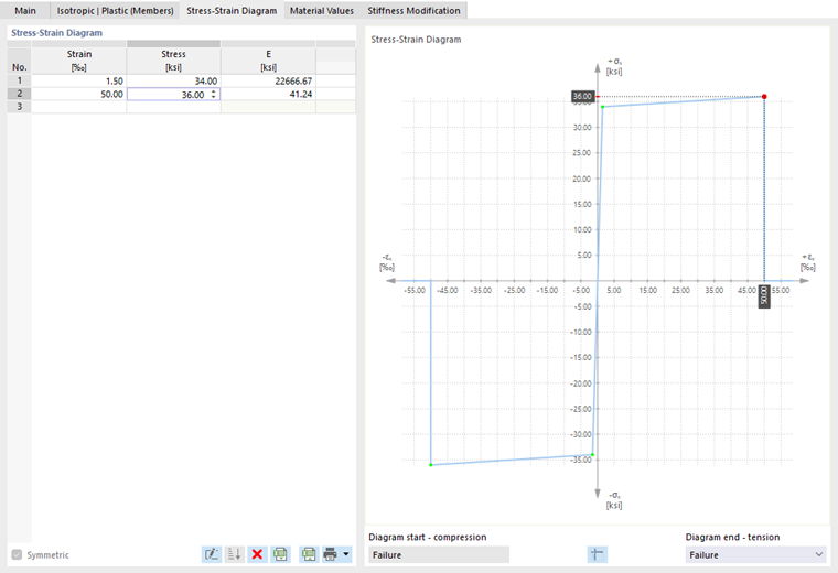
Define a point for the stress-strain relation in each table row. You can select how the diagram continues after the last definition point in the "Diagram end" list below the diagram:
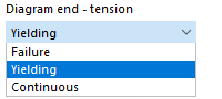
In the case of "Failure", stress after the last definition point jumps back to zero (for example, when material tears). "Yielding" means that stress remains constant when strain increases. "Continuous" means that the graph continues with the slope of the last section.
Isotropic | Plastic (Surfaces/Solids)
If you select Isotropic | Plastic (Surfaces/Solids) from the "Material model" drop-down list, the tab for entering the nonlinear material parameters is activated.
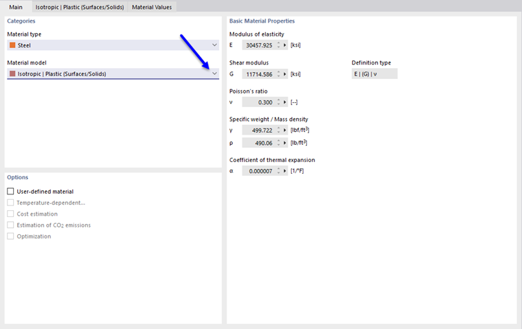
First, select the "Stress failure hypothesis". The following hypotheses are available for selection:
- von Mises (von Mises yield criterion)
- Tresca (Tresca yield criterion)
- Drucker-Prager
- Mohr-Coulomb
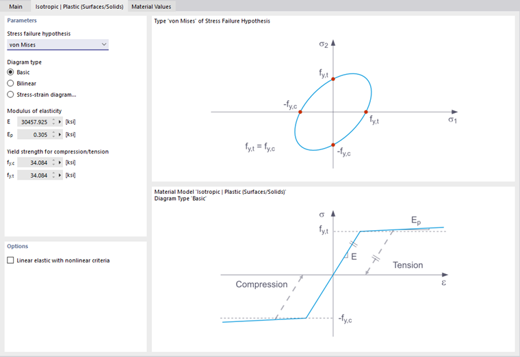
If you select von Mises, the following stresses are used in the stress-strain diagram:
- Surfaces
- Solids
According to the Tresca hypothesis, these stresses are used:
- Surfaces
- Solids
According to the Drucker-Prager hypothesis, the following stress is used for surfaces and solids:
|
σc |
Limit stress for compression |
|
σt |
Limit stress for tension |
According to the Mohr-Coulomb hypothesis, the following stress is used for surfaces and solids:
Isotropic | Nonlinear Elastic (Members)
The functionality largely corresponds to that of the Plastic (Members) material model. But in contrast to it, no plastic strain remains after the load is removed.
Isotropic | Nonlinear Elastic (Surfaces/Solids)
The functionality largely corresponds to that of the Plastic (Surfaces/Solids) material model. But in contrast to it, no plastic strain remains after the load is removed.
Isotropic | Damage (Surfaces/Solids)
In contrast to other material models, the stress-strain diagram for this material model is not antimetric to the origin. This material model can, therefore, be used to model the behavior of steel fiber-reinforced concrete, for example. Detailed information on modeling steel fiber-reinforced concrete can be found in this technical article on the Material Properties of Steel-Fiber-Reinforced Concrete.
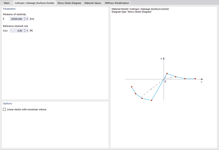
The isotropic stiffness is reduced with a scalar damage parameter. This damage parameter is determined from the stress curve defined in the Diagram. This does not take the direction of the principal stresses into account; rather, the damage occurs in the direction of the equivalent strain, which also covers the third direction perpendicular to the plane. The tension and compression areas of the stress tensor are treated separately. Different damage parameters apply in each case.
The "Reference element size" controls how the strain in the crack area is scaled to the length of the element. With the default value zero, no scaling is performed. Thus, the material behavior of the steel fiber-reinforced concrete is modeled realistically.
Orthotropic | Anisotropic Damage
Timber materials have direction-dependent (anisotropic) properties. The principal anisotropic directions are along the grain, radial, and tangential. In the Orthotropic | Anisotropic Damage tab, you can define the nonlinear properties.
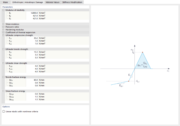
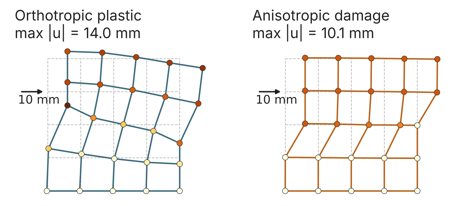
This material model implements Sandhaas’s damage model [2] with eight failure criteria for timber. Timber behaves as quasi-brittle under tension and shear and as ductile under compression. It fails in planes determined by the grain direction. The model according to [2] describes eight separate failure criteria (one for each quadrant of the stress space), which are controlled by nine stiffness reduction factors.
The local x-axis has a parallel distribution relative to the grain, the y-axis has a radial distribution, and the z-axis has a tangential distribution. Each criterion is a stress function F that reaches a value of 1 at the onset of damage. Four of these are simple maximum stress criteria. The four criteria for transverse tension and shear are elliptical: Fracturing in a planar environment can be triggered by tension perpendicular to it, by shear along the plane, or
by any combination thereof.
Specify the ultimate strength of the material, as well as the tensile fracture energy and shear fracture energy for each direction.
Orthotropic | Plastic (Surfaces) / Plastic (Solids)
The material model according to "Tsai-Wu" unifies plastic with orthotropic properties. This allows for special modeling of materials with anisotropic characteristics, such as fiber-reinforced plastics or timber.
If the material is plastified, the stresses remain constant. A redistribution takes place depending on the stiffnesses that are present in the individual directions.
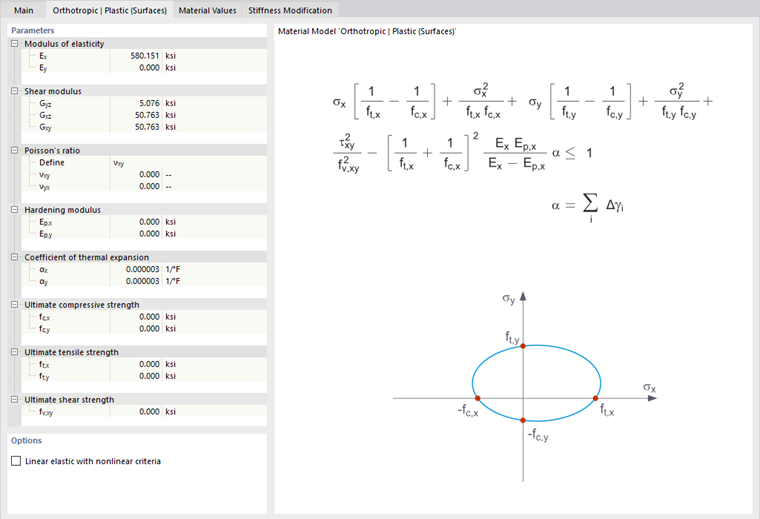
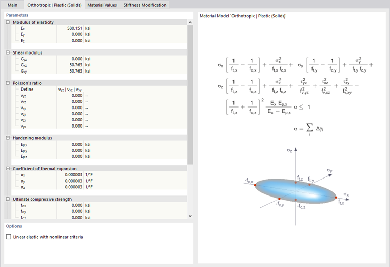
The elastic area corresponds to the material model Linear Elastic (Solids). The following yielding condition according to Tsai-Wu applies to the plastic zone:
- Surfaces
- Solids
All strengths are to be defined as positive.
The yield condition can be imagined as an elliptical surface in the six-dimensional stress space. If one of the three stress components is applied as a constant value, the surface can be projected onto a three-dimensional stress space.
If the value for fy(σ) according to the Tsai-Wu, plane stress state equation is less than 1, the stresses are in the elastic range. The plastic range is reached as soon as fy(σ) = 1. Values greater than 1 are not allowed. The model behavior is ideal-plastic, which means there is no stiffening.
Orthotropic | Plastic | Weld (Surfaces)
This material model is used in analyses with the Steel Joints add-on to represent the behavior of welds in accordance with standards. Only stresses that correspond to the stress components σ⊥, τ⊥, and τ|| of the weld occur in the equivalent surface. In the other stress directions, the stiffness of the equivalent surface approaches zero.

In the "Orthotropic | Plastic | Weld (Surfaces)" tab, you can define the parameters for taking plastic strain hardening for welds into account, such as the limit values fekv and fx for the stress analysis according to the "Directional Method" as per EN 1993-1-8 [1] for welds, modified by a plastic component (see also the technical article Design of Fillet Welds).
Concrete
The nonlinear material models Anisotropic | Damage and Isotropic | Damage (Surfaces/Solids) are available for the "Concrete" material type.
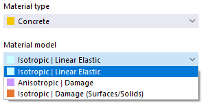
The material models are described in the chapter Anisotropic | Damage of the Concrete Design manual or above in the Isotropic Damage section.
Masonry
If the Masonry Design add-on (requires a license) is activated in the Model Base Data, the nonlinear material models "Isotropic | Masonry | Plastic (Surfaces)" and "Orthotropic | Masonry | Plastic (Surfaces)" are available for selection for the "Masonry" material type.
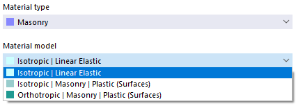
Both material models are described in the chapter Materials of the Masonry Design manual.
Fabric
The material library contains two rows for the material type “fabric”:
- Glass-PTFE: Glass fabric coated with polytetrafluoroethylene (PTFE)
- PES-PVC: Polyester fabric coated with polyvinyl chloride (PVC)
For fabric materials the nonlinear material model Orthotropic | Fabric | Nonlinear Elastic (Surfaces) is available in addition to the orthotropic linear material model.
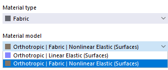
This material model allows for a realistic modeling of the orthotropic behavior of prestressed fabric membranes, whose stiffnesses in the warp and weft directions differ. It describes the fabric using a representative solid element (RVE) of its microstructure. By considering the fabric geometry, the model simnulates the corresponding transverse strain effect for all force states in the membrane. Since the load-dependent stiffness behavior of the fabric is also taken into account, it is possible to perform an accurate analysis of membrane structures.
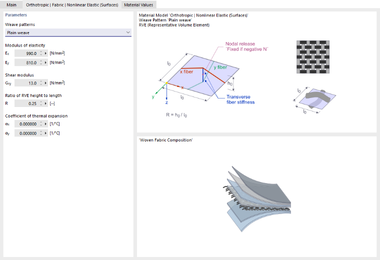
The properties of fabrics are determined in biaxial tests, which result in the moduli of elasticity Ex and Ey, as well as the shear modulus Gxy. However, the coupling between the warp and weft directions arises from the geometry of the fibers: under load, the crimp (ondulation) of the fibers changes in both directions. This effect is referred to in English as “crimp interchange.” The material model therefore derives the material response from a unit cell of the fabric structure. This unit cell also includes its own geometric nonlinearity. Poisson's ratios are not used in this model. The coupling between the two directions is achieved via the parameter R of the unit cell.
As with all nonlinear elastic material models, the strain reverts to its original state along the same path during load relief. The calculation is performed iteratively.
Select the fabric’s manufacturing type from the “Weave patterns” list. Two options are available:
- Plain weave
- Panama weave
Specify the modulus of elasticity in the x- and y-direction. Since the shear moduli Gyz and Gxz are always zero for fabrics, only the Gxy input box for the Poisson's ratio in the fabric plane is provided. This shear modulus may also be zero.
The parameter R describes the ratio of the height to the length of the representative solid element (RVE). This value must be between 0 and 1.
|
h0 |
Height of the unit cell perpendicular to the membrane plane |
|
l0 |
Length of the unit cell |
For materials from the library, R = 0.25 is the default setting and, like the other properties, cannot be changed. For a user-defined material, you can adjust R.
If necessary, adjust the thermal expansion coefficients of the fabric: αx in the warp direction and αy in the weft direction. They may also be zero.
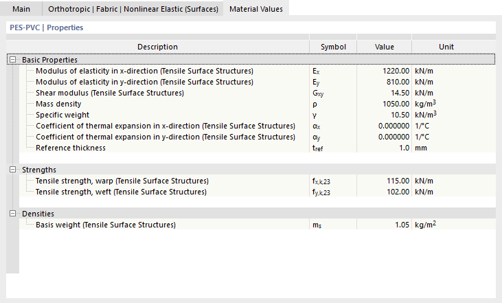
In the “Material Values” tab, the properties of a fabric are specified according to industry standards in the membrane industry. The x-direction corresponds to the warp direction, and the y-direction corresponds to the weft direction.
Fabric Thickness
The thickness of a membrane is very small and can hardly be determined with certainty. In the membrane industry, stiffness and strength are therefore related to the width, for example, in kN/m. RFEM follows this convention and converts the values to stress quantities using the reference thickness tref.
|
Ex,MV / Ey,MV / Gxy,MV |
Stiffness values in the “Material Properties” tab |
|
tref |
Reference thickness |
These values appear in the Material Values tab. When you assign a fabric to a thickness, RFEM uses the material’s reference thickness tref as the thickness d.
The membrane stiffness Ex·tref corresponds to the width-related value in the library. Deformations and membrane forces, such as nx and ny in kN/m, therefore do not depend on the numerical value of the reference thickness, as long as all properties are related to the same reference thickness. Stresses, on the other hand, are related to the reference thickness.
If you change the reference thickness for a user-defined material in the “Material Values” tab, this affects the material properties in the material model tab. Therefore, first define the reference thickness and then the stiffnesses.
Notes on Form-Finding and Design
The form-finding process is independent of the material. The fabric properties have no influence on the resulting shape. They only affect the subsequent calculation under load. The fundamentals are described in the chapter Form-Finding Process of the Form-Finding manual.
A constant orthotropic prestress is physically unachievable for doubly curved surfaces. If you combine orthotropic prestressing with a very large number of form-finding iterations using the standard method, tangential sliding motions in the membrane plane, unstable convergence, and large deformations in the plane may occur. This behavior is independent of the material model. Use the preset number of iterations or select the projection method.